
Lens moving unit and camera module having the same

A technology for lens movement and supporting components, which is applied in the direction of cameras, electromechanical devices, focusing devices, etc., and can solve the problems of low miniaturization and complex structure

Active Publication Date: 2015-09-09
LG INNOTEK CO LTD
View PDF5 Cites 77 Cited by
  • Summary
  • Abstract
  • Description
  • Claims
  • Application Information

AI Technical Summary

Problems solved by technology

Therefore, the structure is complex and miniaturization is unlikely

Method used


Image

  • Lens moving unit and camera module having the same
  • Lens moving unit and camera module having the same
  • Lens moving unit and camera module having the same

Examples


Embodiment approach

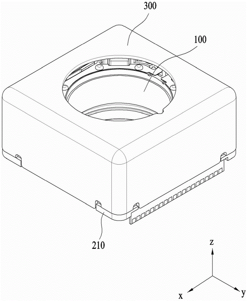
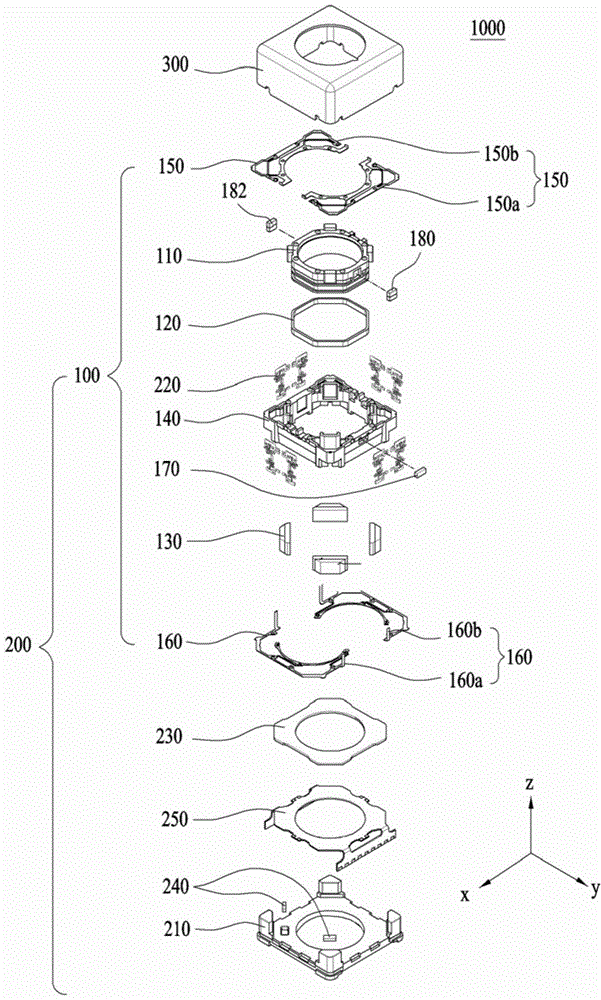
[0075] figure 1 is a perspective view schematically showing a lens moving device 1000, 2000 according to an embodiment, and figure 2 for figure 1 An exploded perspective view of the lens moving device 1000 shown in .

[0076] refer to figure 1 and figure 2 , the lens moving device 1000 may include a first lens moving unit 100 , a second lens moving unit 200 and a cover member 300 . The first lens moving unit 100 may serve as the aforementioned autofocus device, and the second lens moving unit 200 may serve as the aforementioned optical image stabilizer.

[0077] The cover member 300 may be roughly configured in the form of a box. The cover member 300 may cover the first lens moving unit 100 and the second lens moving unit 200 .

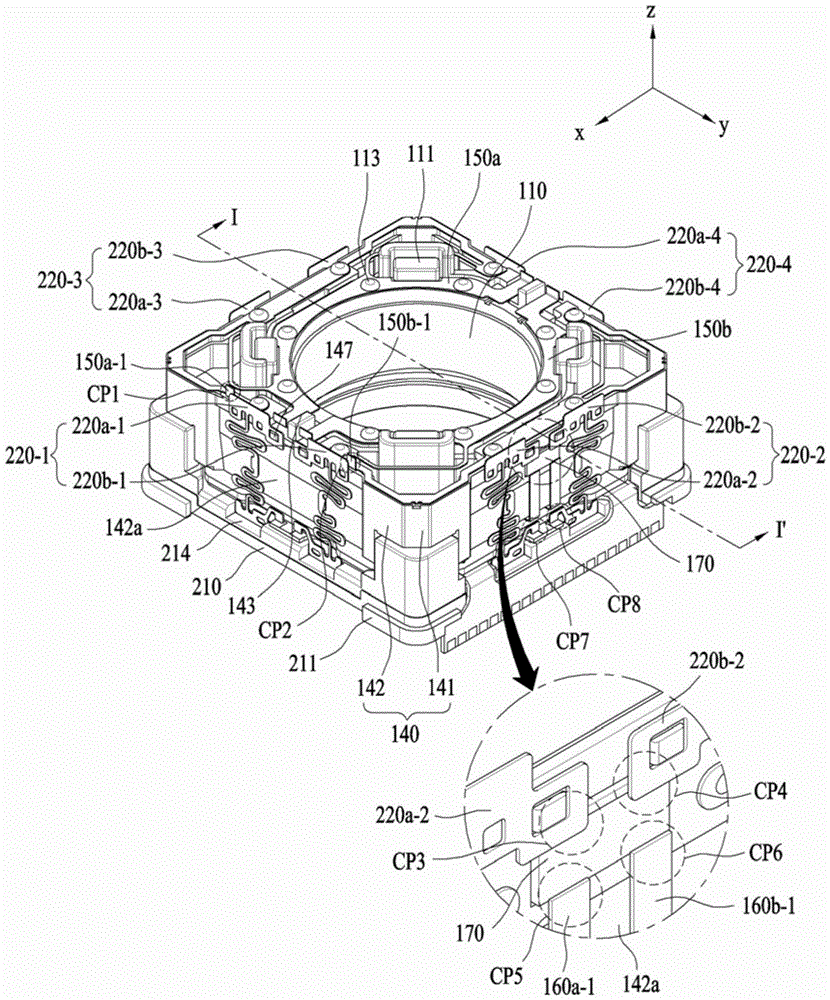
[0078] image 3 is a perspective view of a lens moving device 1000 according to an embodiment, wherein, figure 1 and figure 2 The cover member 300 shown in is removed.

[0079] The first lens moving unit 100 may include a bobbin 110 , a fir...


PUM


Abstract

A lens moving apparatus includes a first lens moving unit including a bobbin having a first coil mounted at an outer circumference thereof, a first magnet being opposite to the first coil, and a housing for supporting the first magnet, and a second lens moving unit including a base, a plurality of support member pairs for supporting the housing such that the housing is movable relative to the base, and a second coil opposite to the first magnet, wherein each of the support member pairs includes first and second support members separated from each other, the first and second support members being disposed at the same side of the housing in a state in which the first and second support members are adjacent to each other, and power is supplied to the first coil through a first support member pair, which is one of the support member pairs.

Description

technical field [0001] Embodiments relate to a lens moving device and a camera module including the same. Background technique [0002] It is difficult to apply technology related to a voice coil motor used in a conventional general camera module to a low power consumption type mini camera module. For this reason, studies related thereto have been actively conducted. [0003] A camera module mounted in a small-sized electronic product such as a smartphone may be frequently shaken during use. In addition, the camera module may slightly shake due to shaking of the user's hand during shooting. Therefore, a technology capable of installing an optical image stabilizer in a camera module is very necessary. [0004] Much research has been done on optical image stabilizers. A technology capable of moving an optical module along an x-axis and a y-axis perpendicular to an optical axis has been proposed for an optical image stabilizer. According to this technique, the optical syst...

Claims


Application Information

Patent Timeline
IPC IPC(8): H04N5/225G02B7/09G03B13/36
CPCG02B27/646G02B7/04H04N5/2328H04N23/55H04N23/57H04N23/685H04N23/687G02B13/0015G02B7/09H02K11/215H02K1/17H02K1/34H02K41/0356
Inventor 赵在弘辛承铎吕寅在韩珍石
Owner LG INNOTEK CO LTD
Learn More