Adjustable radio frequency phase difference power amplifier circuit for linear ablation

A power amplification circuit and phase difference technology, which is applied in the field of medical electronics, can solve the problems of increased internal power consumption, obvious switching loss, and increased circuit volume, and achieve the effects of reducing switching loss, improving work efficiency, and reducing internal loss

Active Publication Date: 2018-04-17
FUDAN UNIV
View PDF5 Cites 0 Cited by
  • Summary
  • Abstract
  • Description
  • Claims
  • Application Information

AI Technical Summary

Problems solved by technology

Due to the point-by-point discrete ablation, it is difficult to form a continuous ablation injury between the two ablation targets, which sometimes results in incomplete isolation of the circumpulmonary vein and residual abnormal conduction pathways, resulting in a decrease in the success rate of treatment of atrial fibrillation
[0004] The existing cardiac radiofrequency ablation power amplifier circuit has a small rated load range. When the myocardial impedance changes during the ablation process, the radiofrequency frequency drift is unstable and the internal power consumption increases
[0005] The existing cardiac radiofrequency ablation power amplifier circuit usually adopts the topology of radio frequency signal generator and power amplifier circuit. The whole circuit works in linear amplification mode, and its switching loss is obvious, which requires a lot of heat dissipation, which increases the volume of the whole circuit

Method used


Image

  • Adjustable radio frequency phase difference power amplifier circuit for linear ablation
  • Adjustable radio frequency phase difference power amplifier circuit for linear ablation
  • Adjustable radio frequency phase difference power amplifier circuit for linear ablation

Examples


Embodiment Construction

[0021] The invention proposes an adjustable radio frequency phase difference power amplifier circuit for realizing linear ablation, which is applied to cardiac radio frequency ablation equipment to realize continuous linear ablation of myocardial tissue. In the specific implementation of the ablation instrument, a heart radiofrequency ablation device can be equipped with multiple circuits of the present invention, combined with a multipolar ablation catheter, to achieve multiple (for example, 10) radio frequency voltage outputs with phase differences. Due to the existence of phase differences, the Both bipolar (between adjacent ablation electrodes) and unipolar (between ablation and reference electrodes) energies exist simultaneously to complete continuous linear ablation.

[0022] Below in conjunction with accompanying drawing, the present invention is described further.

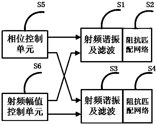
[0023] attached figure 1 is the block diagram of the circuit structure. The phase control unit S5 gene...


PUM


Abstract

The invention belongs to the technical field of medical electronics, in particular to an adjustable radio frequency phase difference power amplifying circuit for realizing linear ablation. The circuit structure of the invention includes: a phase control unit, a radio frequency amplitude control unit, a radio frequency resonance and filter circuit, and an impedance matching network. Among them, the impedance matching network is used to make the myocardial impedance changing during the ablation process equivalent to the rated load range of the circuit, reduce the internal loss of the circuit, and stabilize the output frequency; the soft switching technology is used to make the electronic switch tube realize zero-voltage turn-on or zero-voltage derivative Turn on, reduce switching loss and improve work efficiency. This circuit can overcome the shortcomings of the traditional point-by-point discrete radio frequency ablation technology that it is difficult to form continuous ablation lesions. By adjusting the phase difference of the radio frequency output voltage of adjacent ablation electrodes, the effect of continuous linear ablation can be produced, thereby realizing continuous linear ablation of myocardial tissue.

Description

technical field [0001] The invention belongs to the technical field of medical electronics, and in particular relates to an adjustable radio frequency phase difference power amplifying circuit for realizing linear ablation, which can be applied to heart radio frequency ablation equipment to realize the effect of continuous linear ablation of myocardium. Background technique [0002] Atrial fibrillation is the most common arrhythmia in clinical practice. Its itself and its complications significantly increase the incidence of stroke and mortality in patients. Studies have shown that the ectopic excitatory focus in the pulmonary vein muscle sleeve is an important source of the occurrence and maintenance of atrial fibrillation, so isolating the abnormal excitation conduction path between the pulmonary vein and the atrium is one of the effective methods for the treatment of atrial fibrillation. At present, radiofrequency ablation is the most effective way to complete pulmonary v...

Claims


Application Information

Patent Timeline
Patent Type & Authority Patents(China)
IPC IPC(8): H03F1/02H03F1/56H03F3/20A61B18/12
Inventor 鄢盛杰邬小玫
Owner FUDAN UNIV
Why Eureka
Try Eureka