
Object relational mapping method, device and processor

An object-relational mapping and connection-relationship technology, which is applied in the field of object-relational mapping methods, devices, and processors, can solve the problems of poor reuse, low flexibility, and difficult maintenance, and achieve high reuse, high flexibility, The effect of easy maintenance

Active Publication Date: 2018-10-16
北京国资融资租赁股份有限公司
View PDF3 Cites 0 Cited by
  • Summary
  • Abstract
  • Description
  • Claims
  • Application Information

AI Technical Summary

Problems solved by technology

[0005] In view of this, the purpose of the present invention is to provide an object-relational mapping method, device and processor, which are used to solve the coding confusion in the first method and difficult maintenance in the prior art when object-relational mapping is performed, and the second The problems of low flexibility and poor degree of reuse in this method, the specific implementation plan is as follows:

Method used


Image

  • Object relational mapping method, device and processor
  • Object relational mapping method, device and processor
  • Object relational mapping method, device and processor

Examples


Embodiment 1

[0055] Embodiment 1 of the present application discloses an object-relational mapping method, which is used to solve the coding confusion in the first method and difficult maintenance in the prior art when performing object-relational mapping, and the flexibility in the second method Low, the problem of poor reuse.

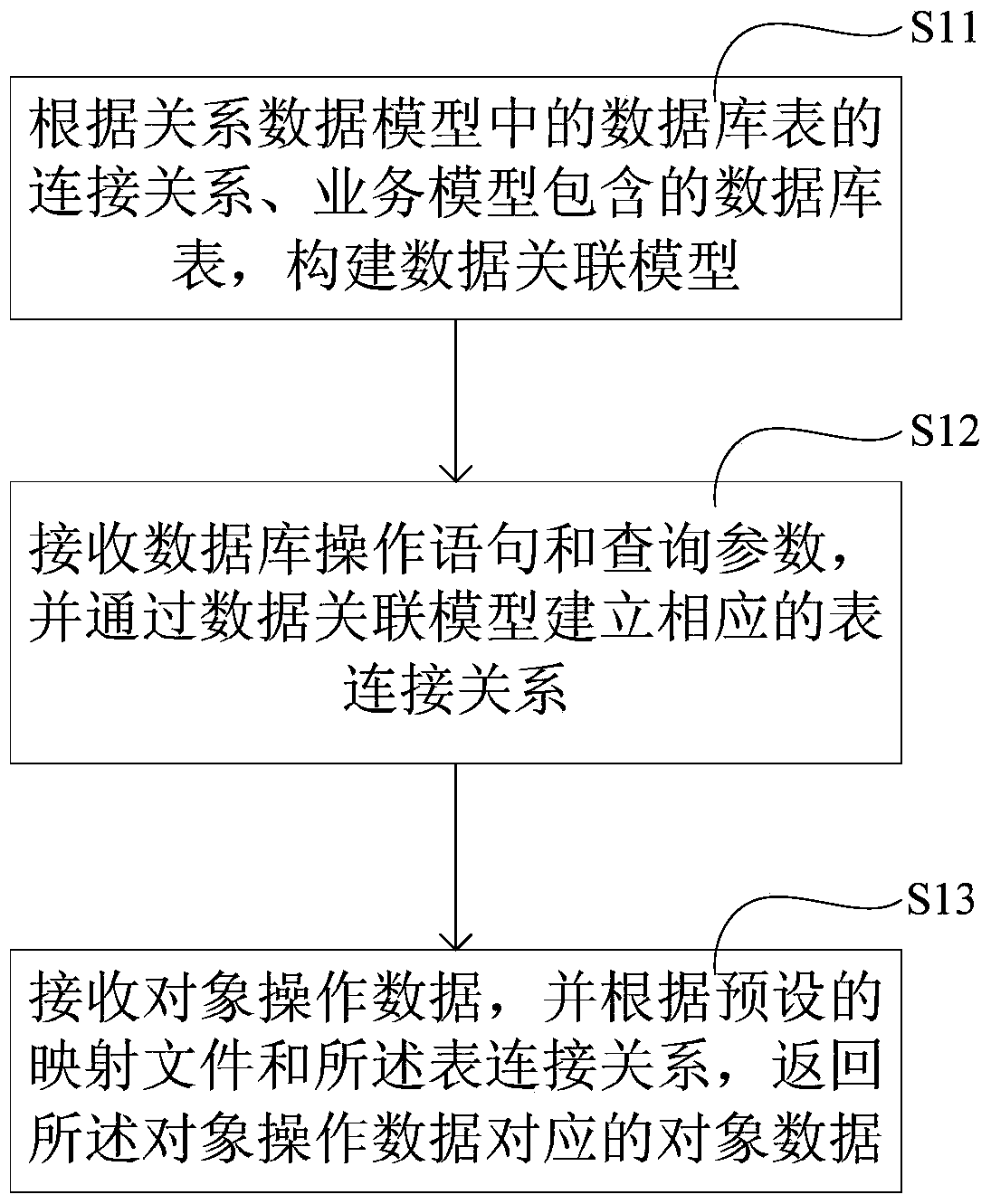
[0056] see figure 1 As shown in the schematic diagram of the workflow, the object-relational mapping method includes:

[0057] Step S11: Construct a data association model corresponding to the business subject to be queried according to the connection relationship of the database tables in the relational data model and the database tables contained in the business model corresponding to the business subject to be queried, wherein the data The node of the association model is the alias of the database table defined in the business model.

[0058] The relational data model includes a data structure, so that the connection relationship of the database tables can be...

Embodiment 2

[0117] Embodiment 2 of the present application discloses an object-relational mapping device correspondingly, see Figure 4 As shown in the structural diagram, the object-relational mapping device includes: a data association model building module 100 , a table connection relationship building module 200 and an object data returning module 300 .

[0118] Wherein, the data association model construction module 100 is configured to construct the corresponding database table of the business subject to be queried according to the connection relationship of the database tables in the relational data model and the database tables included in the business model corresponding to the business subject to be queried. The data association model, wherein, the node of the data association model is an alias of the database table defined in the business model;

[0119] The table connection relationship building module 200 is used to receive database operation statements and query parameters w...


PUM


Abstract

The present invention discloses an object relational mapping method and device as well as a processor. According to the method, when data in a database table are required to be queried, an alias name of the database table corresponding to a current query and a physical field of the database table are determined according to received database operation statements and query parameters, and a corresponding table connection relationship is constructed; and then corresponding object data are returned according to received object operation data and a preset mapping relationship. The method achieves object relational mapping, can be applied to a complicated data model and is used for solving the problem of confused coding in the existing hard coding technology; in addition, according to the object relational mapping method disclosed by the present invention, current query conditions and table connection relationships can be assembled according to object data and mapping files, so that the flexibility is high, and the degree of multiplexing is high.

Description

technical field [0001] The invention relates to the field of computer technology, in particular to an object-relational mapping method, device and processor. Background technique [0002] In software engineering, it is often necessary to store data in a relational database for application access. With the development of information systems, the idea of ​​object-oriented development has been widely used, which has brought about the conversion requirements of relational data and object data. [0003] The conversion of relational data and object data is usually called object-relational mapping (Object RelationalMapping, ORM). In order to realize object-relational mapping, two methods are adopted in the prior art. One of them is to directly embed database statements in the object-oriented program code, so as to realize the mapping between the results returned by the database and the object data in a hard-coded manner; the second method is to use a third-party framework to pre-...

Claims


Application Information

Patent Timeline
Patent Type & Authority Patents(China)
IPC IPC(8): G06F17/30
Inventor 郑叔亮姚红伟
Owner 北京国资融资租赁股份有限公司
Learn More