A spiral tube heat exchanger with variable diameter tube winding

A tubular heat exchanger and heat exchanger technology, applied in the direction of heat exchanger types, indirect heat exchangers, fixed tubular conduit components, etc., can solve the problem of not considering the change of fluid density and physical properties, and the inability to mix working fluids under high pressure in the tube The flow condition improves the adjustment, inapplicability and other problems, and achieves the effect of compact structure, efficient heat exchange and reduced quantity

Active Publication Date: 2017-01-11
TECHNICAL INST OF PHYSICS & CHEMISTRY - CHINESE ACAD OF SCI
View PDF7 Cites 0 Cited by
  • Summary
  • Abstract
  • Description
  • Claims
  • Application Information

AI Technical Summary

Problems solved by technology

The above-mentioned heat exchangers only connect the three-stage heat exchangers through the shell, and cannot improve and adjust the flow conditions of the high-pressure mixed working fluid in the tubes
[0005] In addition, the invention patent CN20120569754 also provides a composite heat exchanger structure that combines a single-tube bundle wound tube heat exchanger with a double-tube wound tube heat exchanger. This structure can improve the heat exchange of multiple streams at different temperatures. However, the heat exchanger tubes are still wound with one tube diameter, without considering the density and physical property changes of fluids in different tubes due to temperature changes, and are not suitable for mixed working medium cryogenic refrigeration systems

Method used


Image

  • A spiral tube heat exchanger with variable diameter tube winding

Examples


Embodiment 1

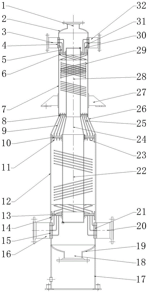
[0026] see figure 1 As shown, the spiral tube heat exchanger with variable diameter tube winding provided by the present invention includes:

[0027] A heat exchanger shell; the heat exchanger shell is composed of a large-diameter shell 12, a transitional-diameter shell 26 and a small-diameter shell 7 connected in sequence;

[0028] The heat exchanger core tube body that is installed in the heat exchanger shell concentrically; the heat exchanger core tube body is composed of a large-diameter core tube body 22, a transition core tube body 24 and a small-diameter core tube body connected in sequence body 28; the large-diameter core body 22, the transition core body 24 and the small-diameter core body 28 are respectively equal to the corresponding large-diameter housing 12, transition-diameter housing 26 and small-diameter housing 7;

[0029] The first fixed flower plate 6 installed between the upper end of the small-diameter core body 28 and the upper end of the small-diameter ...


PUM


Abstract

The invention discloses a spiral tubular heat exchanger for reducing tube winding. The spiral tubular heat exchanger for reducing tube winding comprises a housing and a spiral tube bundle with two ends mounted on a tube plate in the housing, wherein a tube pass inlet and a tube pass outlet or one or more tube pass inlets and outlets are formed in the housing; the tube pass inlet and outlet are used for distributing and collecting the heat exchange tube through a distributor; the spiral tube bundle is divided into multiple layers of concentric heat exchange tubes for being wound on a core tube; each layer of heat exchange tubes is spirally wound in the same direction; a separating wire is mounted between adjacent two layers of heat exchange tubes, and the winding direction is the same or reverse. Single heat exchange tube is formed by connecting one or more diameter tubes with different lengths; different diameter winding tubes are transited, fixed and connected through patterned plates. The spiral tube type heat exchanger disclosed by the invention can realize efficient heat exchange of different temperature sections under a large temperature span condition, and has the advantages of being compact in structure, high in heat exchange efficiency, beneficial to integrated assembly of heat exchangers in different temperature regions, capable of reducing the size of the heat exchanger, reducing the quantity of heat exchange equipment, and the like.

Description

technical field [0001] The invention relates to a heat exchanger, in particular to a spiral tube heat exchanger with variable diameter tubes wound. Background technique [0002] The spiral wound tube heat exchanger has many advantages such as compact structure, large heat transfer area per unit volume, certain temperature self-compensation ability, and small footprint. obtained a wide range of applications. During the mixed working medium refrigeration process, the high-pressure mixed working medium flows through the tube, and the low-pressure mixed working medium flows through the shell side formed by the gap outside the tube. The temperature of the high-pressure mixed working medium in the tube undergoes a phase change condensation heat transfer process from the vapor phase to the vapor-liquid two-phase and then to the liquid phase from high to low, and the fluid density continues to increase. The volumetric flow rate will continue to decrease, resulting in the accumulat...

Claims


Application Information

Patent Timeline
Patent Type & Authority Patents(China)
IPC IPC(8): F28D7/02F28F1/00
Inventor 邹鑫公茂琼吴剑峰
Owner TECHNICAL INST OF PHYSICS & CHEMISTRY - CHINESE ACAD OF SCI
Why Eureka
Try Eureka