Mechanism for controlling flow directions of airflow and biomass burner using same

A technology of flow direction and airflow control, applied in combustion methods, combustion equipment, fuel supply, etc., can solve the problems of biomass burners not working normally, increasing maintenance costs and operating costs, hindering continuous production, etc., and achieving simple structure , low cost, convenient production process

Inactive Publication Date: 2015-09-09
嘉善凝溪建设有限公司
View PDF5 Cites 0 Cited by
  • Summary
  • Abstract
  • Description
  • Claims
  • Application Information

AI Technical Summary

Problems solved by technology

[0002] The existing biomass burners all have a biomass feeding structure, through which the biomass particles in the silo are sent into the combustion chamber. The traditional biomass feeding mechanism adopts the screw propulsion conveying mechanism I, and the silo 1 The biomass particles inside are squeezed and crushed by the screw feeder 2, and then pushed to the combustion chamber by the screw propulsion conveying mechanism I for combustion, but the inventor found in the actual use that the screw propulsion conveying mechanism I often Biomass particles fall into its internal spiral and get stuck, which will cause the biomass burner to not work normally, hinder continuous production, high failure rate, and increase maintenance costs and operating costs

Method used


Image

  • Mechanism for controlling flow directions of airflow and biomass burner using same
  • Mechanism for controlling flow directions of airflow and biomass burner using same
  • Mechanism for controlling flow directions of airflow and biomass burner using same

Examples


Embodiment 1

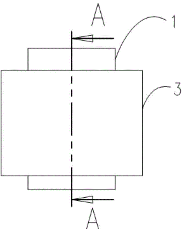
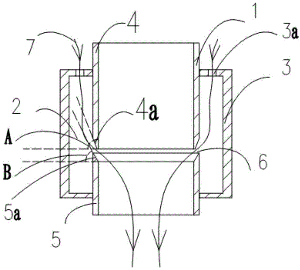
[0030] figure 1 It is a schematic diagram of the appearance of Embodiment 1 of a mechanism for controlling the flow direction of airflow in the present invention; figure 2 It is a schematic diagram of the internal structure of Embodiment 2 of a mechanism for controlling the flow direction of airflow in the present invention; figure 1 and figure 2 As shown, a mechanism for controlling the flow direction of airflow includes a cylinder 1 and a sleeve 3 arranged on the outer wall of the cylinder and forming a closed space 2 with the cylinder, and the cylinder 3 includes a first cylinder segment 4 and the second cylinder section 5 are two sections up and down, the two are coaxially arranged, and there is a distance 6 between the first cylinder section 4 and the second cylinder section 5; the first cylinder section 4 The outer wall near the end of the second cylindrical section 5 is provided with an outer chamfer 4a with a slope A; Chamfering 5a, an annular opening 6 is formed ...

Embodiment 2

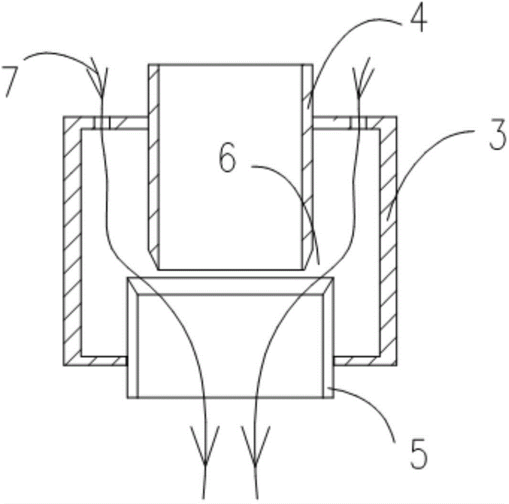
[0033] image 3 It is a schematic diagram of the internal structure of Embodiment 2 of a mechanism for controlling the flow direction of airflow in the present invention; image 3 As shown, the outer diameter of the first cylindrical section 4 is D1, the outer diameter of the second cylindrical section 5 is D2, and D1=0.7*D2.

Embodiment 3

[0035] Figure 4 It is a schematic structural diagram of a biomass burner using the mechanism for controlling the flow direction of the airflow. Such as Figure 4 As shown, a biomass burner includes a silo 8, a screw feeder 9 connected to the bottom of the silo, and a feeding channel 10 connected to the outlet end of the screw feeder 9. The feeding channel 10 is connected to the combustion chamber. In the chamber 11, the combustion chamber 11 is also provided with a flame nozzle 11a, including the above-mentioned mechanism for controlling the flow direction of the airflow and the wind source 12. The mechanism for controlling the flow direction of the airflow is arranged at the outlet end of the screw feeder 9 and Between the feeding channels 10; the biomass particles sheared by the screw feeder 9 enter the cylinder 3, and the wind source 12 is introduced and blown in from the annular opening 6 to send the biomass particles into the feeding channel 10. Combustion in the combu...


PUM


Abstract

The invention relates to a mechanism for controlling flow directions of airflow. The mechanism for controlling the flow directions of the airflow comprises a cylinder (1), and a sleeve (3) which is arranged on the outer wall of the cylinder (1), and forms a sealed space (2) together with the cylinder (1), wherein the cylinder (1) comprises a first cylinder segment (4) and a second cylinder segment (5), which are respectively arranged at the upper end and the lower end of the cylinder (1), and form an annular opening (6), and the airflow (7) enters the sealed space (2) through an airflow inlet (3a), and then is discharged into the second cylinder segment (5) through the annular opening (6). The invention further relates to a biomass burner using the mechanism for controlling the flow directions of the airflow. The biomass burner using the mechanism for controlling the flow directions of the airflow comprises a feed bin (8), a spiral feeder (9) and a feed channel (10), and further comprises a mechanism which controls the flow directions of the airflow and an air source (12), wherein biomass particles after being sheared by the spiral feeder (9) enter the cylinder (1), and the air source (12) guides the airflow into the cylinder (1) through the annular opening (6), and then the airflow blows the biomass particles into a combustor through the feed channel (10). The mechanism for controlling the flow directions of the airflow and the biomass burner using the same solve the problem that the biomass particles are blocked, and have the advantages of being good in choking resistance, simple in structure, low in production cost and the like.

Description

Technical field: [0001] The invention belongs to the technical field of biomass energy utilization, and more specifically relates to a mechanism for controlling the flow direction of airflow and a biomass burner using the mechanism. Background technique: [0002] The existing biomass burners all have a biomass feeding structure, through which the biomass particles in the silo are sent into the combustion chamber. The traditional biomass feeding mechanism adopts the screw propulsion conveying mechanism I, and the silo 1 The biomass particles inside are squeezed and crushed by the screw feeder 2, and then pushed to the combustion chamber by the screw propulsion conveying mechanism I for combustion, but the inventor found in the actual use that the screw propulsion conveying mechanism I often Biomass particles fall into its inner spiral and get stuck, which will cause the biomass burner to not work normally, hinder continuous production, high failure rate, and increase maintena...

Claims


Application Information

Patent Timeline
Patent Type & Authority Applications(China)
IPC IPC(8): F23K3/02
Inventor 叶有芳沈润良
Owner 嘉善凝溪建设有限公司
Why Eureka
Try Eureka