A banknote handle turning unit

A banknote handle and tumbling technology, applied in the direction of conveyor objects, transportation and packaging, etc., can solve the problems that the equipment cannot meet the requirements of compact structure, simple structure, reasonable and compact structure layout, and the height of the device cannot meet the current requirements, etc., to achieve compact structure, structure Simple, transition-position-accurate effects

Active Publication Date: 2017-06-16
CITIC TIANJIN OUTSOURCING SERVICES
View PDF2 Cites 0 Cited by
  • Summary
  • Abstract
  • Description
  • Claims
  • Application Information

AI Technical Summary

Problems solved by technology

The patent pivots, but the patent does not meet current requirements in terms of device height
[0005] All the equipment currently on the market cannot meet the requirements of compact structure, simple structure, reasonable and small structure layout

Method used


Image

  • A banknote handle turning unit
  • A banknote handle turning unit
  • A banknote handle turning unit

Examples


Embodiment 1

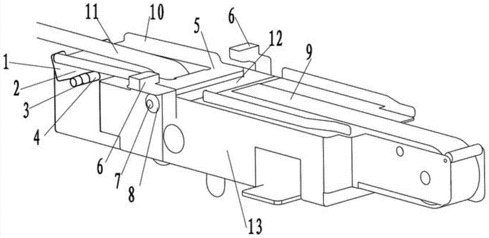
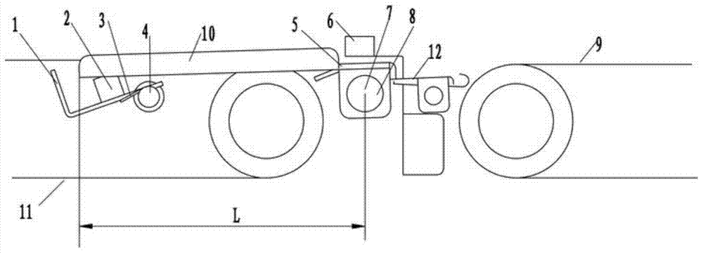
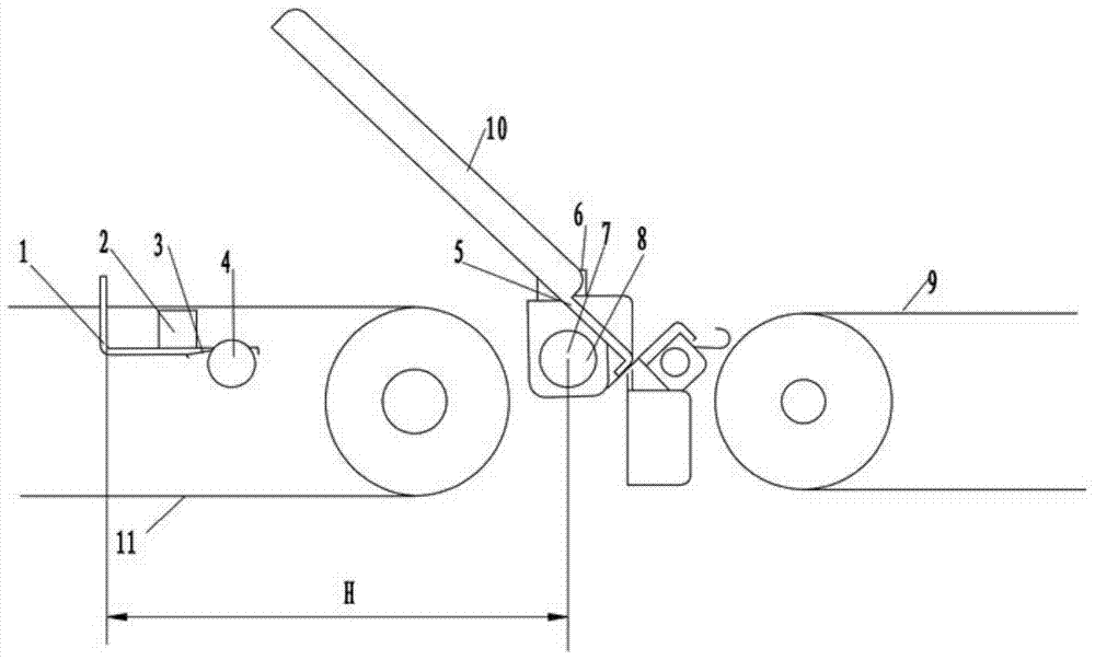
[0042] refer to Figure 1 to Figure 9 ,Such as figure 1A banknote handle turning unit is shown, wherein the rolling unit includes a frame 13, a transmission device, a turning mechanism and a current limiting mechanism, the transmission device is installed on the frame 13, the banknote handle is transported on the transmission device, and the transmission device It includes a first transmission mechanism and a second transmission mechanism, the first transmission mechanism receives and transmits the banknote handle with the first motion state; the second transmission mechanism receives and transmits the banknote handle with the second motion state; the second transmission mechanism includes a drive shaft And the transmission belt 9, the first transmission mechanism includes a drive shaft and a transmission belt 11. Generally speaking, the transmission belt 11 receives the banknote handle and transports it to the transmission belt 9, and transports the banknote handle to the nex...

Embodiment 2

[0057] refer to Figure 1 to Figure 9 ,Such as figure 1 A banknote handle turning unit is shown, wherein the rolling unit includes a frame 13, a transmission device, a turning mechanism and a current limiting mechanism, the transmission device is installed on the frame 13, the banknote handle is transported on the transmission device, and the transmission device It includes a first transmission mechanism and a second transmission mechanism, the first transmission mechanism receives and transmits the banknote handle with the first motion state; the second transmission mechanism receives and transmits the banknote handle with the second motion state; the second transmission mechanism includes a drive shaft And the transmission belt 9, the first transmission mechanism includes a drive shaft and a transmission belt 11. Generally speaking, the transmission belt 11 receives the banknote handle and transports it to the transmission belt 9, and transports the banknote handle to the ne...


PUM


Abstract

The invention discloses a banknote handle rolling unit, which comprises: a frame; a transmission device, the transmission device is installed on the frame, the banknote handle is conveyed on the transmission device, and the transmission device includes a second transmission device Mechanism and a first transmission mechanism, the second transmission mechanism receives the second movement state of the banknote handle and transmits it, and the first transmission mechanism receives the first movement state of the banknote handle and transmits; a flip mechanism, the flip mechanism is installed on the rack On the other hand, the turning mechanism can swing the banknote handle with the moving state on the first conveying mechanism to the banknote handle with the second moving state that can be received by the second conveying mechanism. The invention has the advantages of high working efficiency, simple structure, reasonable layout, high degree of automation and accurate position conversion.

Description

technical field [0001] The invention relates to the field of financial equipment, in particular to a banknote handle turning unit. Background technique [0002] At present, the attention and management of the cleanliness of the RMB in the RMB circulation market are increasing, and more and more attention has been paid to it. In the banknote automatic processing center, after the banknotes are sorted and bound by the sorting and binding machine, the banknotes (100 pieces) are conveyed out by the conveyor belt, and then 10 banknotes are gathered and bundled into a banknote bundle (100 pieces). When sorting the bundles, the paper tapes are usually tied at a position away from the center of the banknotes. If 10 paper tapes are all at one end, due to the superposition of paper tape thicknesses, the bundled banknotes will be thicker at one end and thinner at the other end. In order to avoid this phenomenon, it is generally necessary to adjust the banknote bundle every 5 ends, so ...

Claims


Application Information

Patent Timeline
Patent Type & Authority Patents(China)
IPC IPC(8): B65G47/248
Inventor 杨承然
Owner CITIC TIANJIN OUTSOURCING SERVICES
Why Eureka
Try Eureka