
Non-inflatable tyre having tread of comfortable elastic structure

A non-pneumatic tire, elastic structure technology, applied in non-pneumatic tires, tire tread/tread pattern, tire parts, etc., can solve the problems of high bonding difficulty, high outer ring hardness, and the same tire bonding strength , to achieve the effect of increasing the effective grounding area, reducing the thickness of the outer ring, and improving the anti-slip ability

Active Publication Date: 2015-09-09
SHENZHEN DAORUI TIRE CO LTD
View PDF6 Cites 5 Cited by
  • Summary
  • Abstract
  • Description
  • Claims
  • Application Information

AI Technical Summary

Problems solved by technology

Among them, 93103843 X also describes inserting inserts into the middle web of the non-pneumatic tire to optimize and enhance the comfort of the tire, but since both of them are equipped with rubber treads on the outer ring, although part of the comfort is solved However, since polyurethane materials and rubber materials are two different materials, and tires are high-strength running wear parts, the bonding between them is a difficult technical problem. Even if this bonding technology can be solved, large quantities It is also difficult to ensure that the bonding strength of each tire is the same during production, and the bonding process is difficult to achieve, so their products are difficult to industrialize
In addition, because the hardness of the outer ring is large and there is no optimized structure, even if the outer ring is glued to the rubber tread, it cannot achieve the comfort close to that of a rubber pneumatic tire.

Method used


Image

  • Non-inflatable tyre having tread of comfortable elastic structure
  • Non-inflatable tyre having tread of comfortable elastic structure
  • Non-inflatable tyre having tread of comfortable elastic structure

Examples


Embodiment Construction

[0025] The following will clearly and completely describe the technical solutions in the embodiments of the present invention with reference to the accompanying drawings in the embodiments of the present invention. Obviously, the described embodiments are only some, not all, embodiments of the present invention. Based on the embodiments of the present invention, all other embodiments obtained by persons of ordinary skill in the art without making creative efforts belong to the protection scope of the present invention.

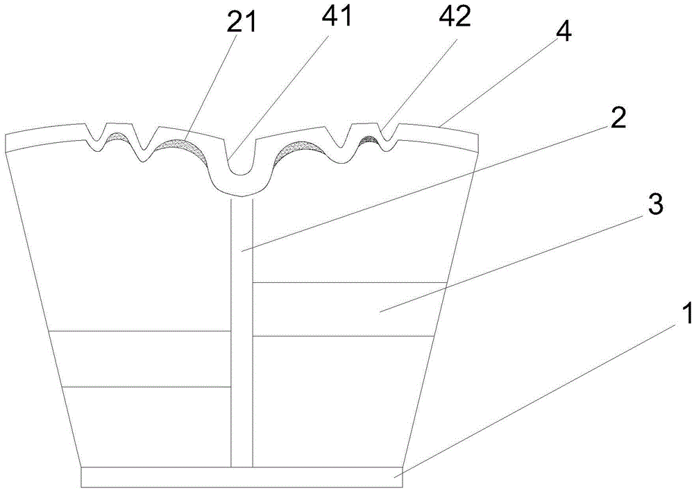
[0026] Such as figure 2 , the traditional non-pneumatic tire is made up of web 2, support plate 3, inner ring 1 and outer ring 4 made of elastomeric material. In this embodiment, the elastic material is polyurethane material. In the process of forming, the web 2. There will be angles of different angles at the intersection of the support plate 3, the inner ring 1 and the outer ring 4, and polyurethane with high hardness is a material that is elastic and not e...


PUM


Abstract

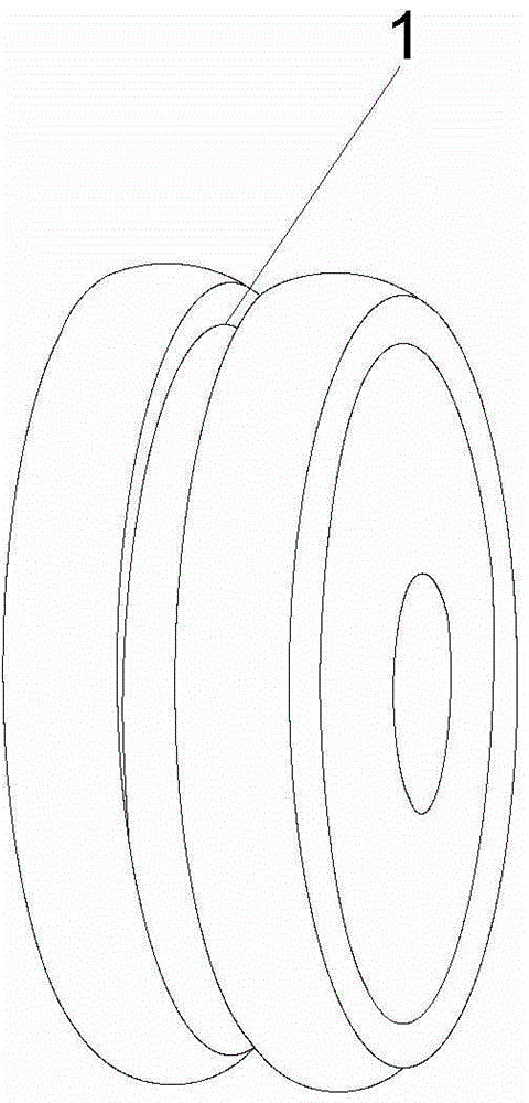
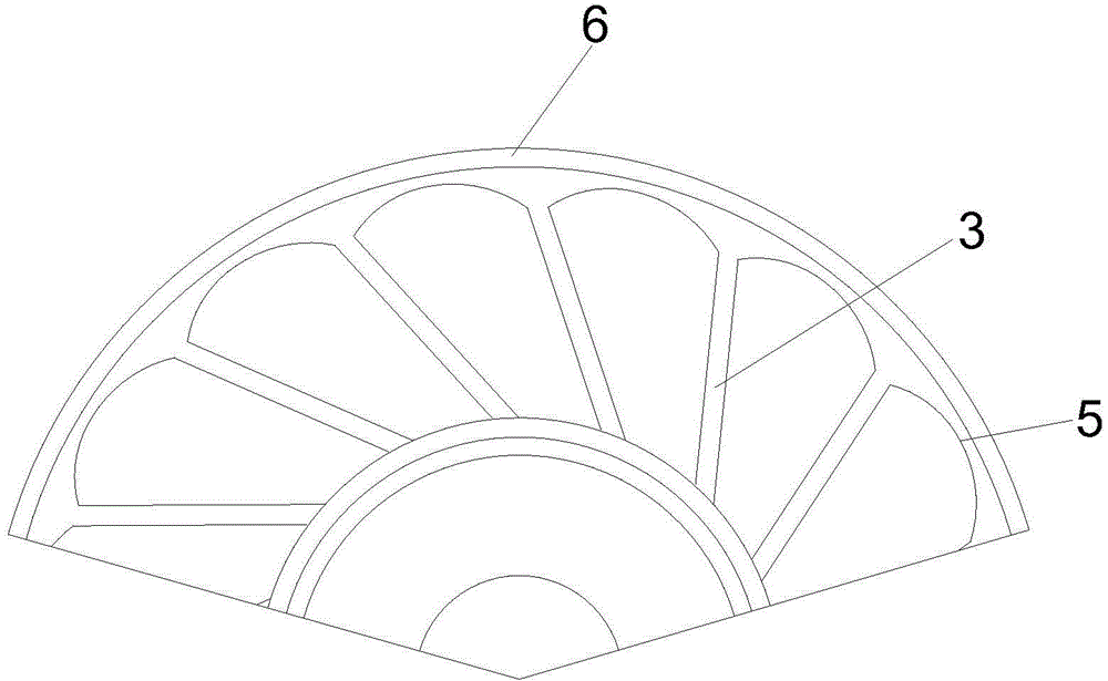
The invention discloses a non-inflatable tyre having a tread of a comfortable elastic structure. The tyre comprises an inner ring, a radial plate, a support plate and an outer ring. The inner ring and the outer ring are of concentric structures; the radial plate is connected with the outer ring and the inner ring in the common central axis plane; support plates used for connecting the outer ring with the inner ring are arranged on the right and left sides of the radial plate; the support plates on the right and left sides of the radial plate are arranged in opposite directions; the support plates are connected with the radial plate vertically; an inclination angle being 15-75 degrees is formed between the support plates and the radial plane of the inner ring formed by connection lines between the support plates and the inner ring; a ring middle groove is formed in the outer ring; the outer ring is partitioned into a left outer ring and a right outer ring through the ring middle groove; the bottom of the ring middle groove is protruded out of the inner surface of the tread and connected with the radial plate. According to the invention, the ring middle groove, outer ring grooves, curved ruts and arched structures are arranged, and thus the outer ring of the non-inflatable tyre has better road holding performance, slip resistance and higher comfort.

Description

technical field [0001] The invention relates to a non-pneumatic tire, in particular to a non-pneumatic tire with a comfortable elastic structure tread. Background technique [0002] Car tires are a general term for tires, usually made of wear-resistant rubber materials, and can be divided into pneumatic tires and solid tires. Inflate enough gas to obtain comfortable support in the sealed rubber cavity. The disadvantage of pneumatic tires is that the rubber material of the tread is easy to wear. Because it is inflated support, there is also the possibility of tire blowout. Secondly, whether it is a rubber solid tire or a polyurethane solid tire They are all slow to run, uncomfortable, and prone to internal heat generation and cannot run for a long time. Later in the research, it was found that polyurethane materials were used to make non-pneumatic tires with integrated and connected elastic rings, which did not need to be inflated to ensure that the driving vehicle would not...

Claims


Application Information

Patent Timeline
IPC IPC(8): B60C7/00B60C11/12
CPCB60C7/00B60C11/03B60C11/12
Inventor 余前孙
Owner SHENZHEN DAORUI TIRE CO LTD
Learn More