Door control light switch system based on wireless communication and method thereof

A wireless communication and switching system technology, applied in the field of smart home, can solve the problem of being unable to intelligently judge whether to turn on the lights, etc., to achieve the effect of humanized control, intelligentization, and avoiding the waste of electric energy

Active Publication Date: 2015-09-02
INVENTEC(NANJING) TECH CO LTD +1
View PDF4 Cites 9 Cited by
  • Summary
  • Abstract
  • Description
  • Claims
  • Application Information

AI Technical Summary

Problems solved by technology

[0004] The purpose of the present invention is to provide a system and method for gated light switch based on wireless communication to solve the problem of being unable to intelligently judge whether to turn on the light

Method used


Image

  • Door control light switch system based on wireless communication and method thereof
  • Door control light switch system based on wireless communication and method thereof
  • Door control light switch system based on wireless communication and method thereof

Examples


Embodiment 1

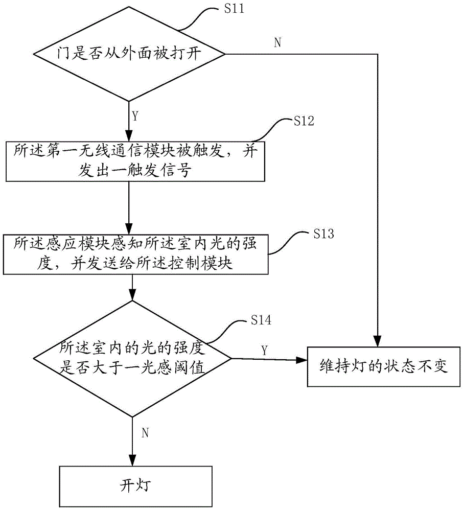
[0040] The present invention provides a system and method for a gated light switch based on wireless communication, wherein the system for gated light switch based on wireless communication, such as figure 1 As shown, it includes: a detection module 107, and the detection module 107 is used to determine whether the door is opened from outside. Specifically, the detection module 107 includes a first grating sensing module 109, the first grating sensing module 109 is located at the hole outside the door lock 102, and is used to determine whether a key is inserted into the door lock 102 inside the outer eyelet.

[0041] The detection module 107 also includes a second grating sensing module 110, the second grating sensing module 110 is located on the door, specifically, on the inner side of the door, and is close to the door and opposite to the door frame The edge of one side is used to judge whether the door is opened. Both the first grating sensing module 109 and the second gr...

Embodiment 2

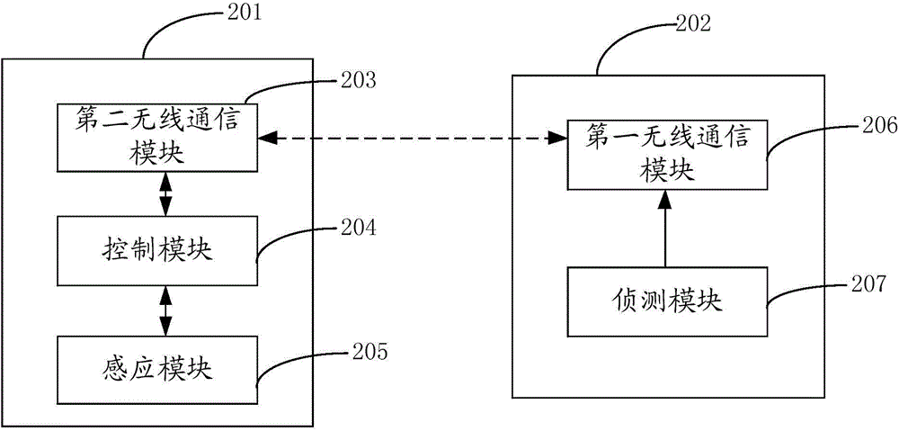
[0057] In this embodiment, the wireless communication-based gated light switch system, such as image 3 shown, including:

[0058] A detection module 207, the detection module 207 is used to determine whether the door is opened from outside. Specifically, the detection module 207 includes a first grating sensing module 210, the first grating sensing module 210 is located at the hole outside the door lock 202, and is used to determine whether a key is inserted into the door lock 202 inside the outer eyelet.

[0059] The detection module 207 also includes a second grating sensing module 211, the second grating sensing module 211 is located on the door, specifically, on the inner side of the door, and is close to the door and opposite to the door frame The edge of one side is used to judge whether the door is opened. Both the first grating sensing module 210 and the second grating sensing module 211 are cut off to generate a signal, indicating that the door is opened from the ...


PUM


Abstract

The invention provides a door control light switch system based on wireless communication and a method thereof. The door control light switch system based on wireless communication comprises a first wireless communication module, a detecting module, a control module, a second wireless communication module and an induction module. When the detecting module detects that a key is inserted into an eyelet of an outer side of a door lock and the door is opened, the first wireless communication module is triggered and sends a trigger signal to the second wireless communication module. After the second wireless communication module receives the trigger signal, the control module makes the induction module perceive an indoor environment and whether indoor light needs to be turned on is determined according to an indoor illumination intensity and whether someone is in the place. Electric energy wastes caused by turning on the light when the indoor light intensity is higher in daytime are avoided. Household intelligence is realized. When someone is at rest at night, a situation that a rester is disturbed by the light which is turned on automatically is avoided so that control is humanized.

Description

technical field [0001] The invention relates to the field of smart homes, in particular to a system and method for door-controlled light switches based on wireless communication. Background technique [0002] With the development of science and technology, people's work rhythm and pressure are very high, and they may go home very late every day. And every night when I go home and open the door, I have to turn on the lights at home in the dark, and sometimes some collisions or accidents often occur. [0003] The utility model patent with authorized notification number CN 203755996U discloses a gated light switch system. The gated light switch system includes a pressure-sensitive switch located inside the door lock groove. Close to control the opening and closing of the light, avoiding the inconvenience of being in the dark when going home at night, but at the same time, a new problem is introduced, that is, when the indoor light is sufficient during the day, when the intensi...

Claims


Application Information

Patent Timeline
Patent Type & Authority Applications(China)
IPC IPC(8): H05B37/02
CPCY02B20/40
Inventor 高竹青
Owner INVENTEC(NANJING) TECH CO LTD
Why Eureka
Try Eureka