
Driving circuit for switching bridge arm and switching power supply

A technology of driving circuit and bridge arm, applied in the field of switching power supply, can solve the problems of negative overshoot of Vsw network, overstress damage of driving chip, short board of reliability of switching power supply, etc., to achieve the effect of improving reliability

Active Publication Date: 2017-07-14
HUAWEI DIGITAL POWER TECH CO LTD
View PDF5 Cites 0 Cited by
  • Summary
  • Abstract
  • Description
  • Claims
  • Application Information

AI Technical Summary

Problems solved by technology

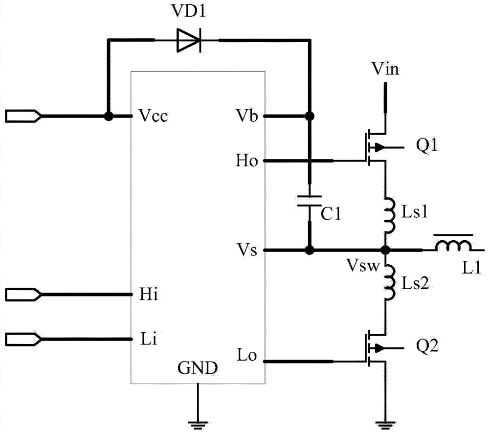
In the existing technology, such as figure 1 As shown, due to the existence of the leakage inductance Ls1 and Ls2 of the power loop, when the upper transistor Q1 is turned off, the current of Ls2 cannot change abruptly, and it is initially zero, which will cause negative overshoot of the Vsw network and cause the negative pressure of the pin Vs of the driver chip to exceed the standard , which will cause a latch-up of the driver chip, and the charging voltage of the bootstrap capacitor will be too high, which will damage the power supply pin Vb of the upper tube.
A similar situation will also occur when the lower tube Q2 is turned off, resulting in positive overshoot of the Vsw network, resulting in overstress damage to the driver chip
Therefore, the bridge arm driver chip has become a short board for the reliability of the switching power supply.

Method used


Image

  • Driving circuit for switching bridge arm and switching power supply
  • Driving circuit for switching bridge arm and switching power supply
  • Driving circuit for switching bridge arm and switching power supply

Examples


Embodiment Construction

[0042] The following will clearly and completely describe the technical solutions in the embodiments of the present invention with reference to the accompanying drawings in the embodiments of the present invention. Obviously, the described embodiments are some of the embodiments of the present invention, but not all of them. Based on the embodiments of the present invention, all other embodiments obtained by persons of ordinary skill in the art without creative efforts fall within the protection scope of the present invention.

[0043] Due to the advantages of fast switching speed, easy parallel connection, and low driving power required, MOSFET has become one of the most commonly used power switching devices for switching power supplies. The quality of the drive circuit directly affects the reliability and performance indicators of the switching power supply.

[0044] figure 2 is a schematic diagram of a driving circuit for driving a switch bridge arm according to an embodi...


PUM


Abstract

The embodiment of the present invention provides a driving circuit for a switch bridge arm, including: a driving chip, a double-winding driving transformer and a driving module; The two ends of the primary side are connected; the two ends of the secondary side of the double-winding drive transformer are respectively connected to the first input end and the second input end of the drive module; the first output end of the drive module is used to connect with the upper tube of the switch bridge arm The gate connection of the drive module, the second output terminal of the driving module is used to connect with the source of the upper tube of the switch bridge arm; the second output terminal of the driver chip is used to connect with the gate of the lower tube of the switch bridge arm; wherein, the drive The module is used to make only the voltage higher than the preset threshold value act on the gate and source of the upper transistor of the switch bridge arm. The drive circuit can solve the overvoltage problem of the power supply pin and the ground terminal pin of the upper tube floating drive circuit, and can improve the reliability of the upper tube drive of the switch bridge arm.

Description

technical field [0001] Embodiments of the present invention relate to the communication field, and more specifically, relate to a driving circuit for a switching bridge arm and a switching power supply. Background technique [0002] Due to the advantages of small size, light weight and high efficiency, switching power supply has become more and more popular. Switching bridge arms widely exist in switching power supplies, and there are multiple sets of switching bridge arms in some topological scenarios. To make the switch bridge arm work normally, it is often the key to choose a suitable and reliable drive circuit. [0003] In the switch bridge arm, in order to prevent the upper and lower bridge arms from being turned on at the same time (also known as through), the drive of the upper and lower bridge arms needs to be set with a dead time (deadtime). In the existing technology, such as figure 1 As shown, due to the existence of the leakage inductance Ls1 and Ls2 of the po...

Claims


Application Information

Patent Timeline
Patent Type & Authority Patents(China)
IPC IPC(8): H02M1/08
Inventor 樊晓东
Owner HUAWEI DIGITAL POWER TECH CO LTD
Learn More