Linear Vibration Energy Harvesting Device of Rolling Vibrator

A technology of energy collection and linear vibration, applied in the direction of electromechanical devices, electrical components, etc., can solve the problems of affecting power generation efficiency, overall and complex structure, and less electric energy, so as to improve energy collection efficiency, coil utilization rate, and utilization rate Effect

Active Publication Date: 2017-08-25
ZHEJIANG UNIV OF TECH
View PDF5 Cites 1 Cited by
  • Summary
  • Abstract
  • Description
  • Claims
  • Application Information

AI Technical Summary

Problems solved by technology

Thesis "Research on the Performance of a New Type of Permanent Magnet Built-in Linear Vibration Generator" (Journal of Zhejiang University Engineering Science Edition, Vol. . The utilization rate is not high, and the vibration energy utilization rate is not high
At the same time, the coil utilization rate in some of the above materials is also a point that can be improved. Many parts of the coil cannot effectively cut the magnetic force lines, generate electromotive force, and affect the power generation efficiency.
The surrounding vibration generator with application number 201020125287.8 has four S poles of permanent magnets distributed symmetrically in a cross, and its bottoms are connected together and connected to N poles. This has high requirements on the manufacturing process and is very difficult to manufacture
At the same time, because the coil is installed between the N pole and the S pole, the overall structure and structure are relatively complicated, even if the permanent magnet can be manufactured, it is difficult to install
Moreover, since there is a coil between the N pole and the S pole, the air gap in the magnetic circuit is still relatively large, which may cause the magnetic circuit to be unable to close or the induced magnetic flux to be weak, resulting in less electric energy, which is necessary for high manufacturing costs. it's not worth the candle
The electromagnetic vibration power generation device with the application number 2012104994623 tries to eliminate the positioning force by balancing the magnetic force, but because the magnetic force in the first device is much greater than the gravity, and due to the existence of errors and asymmetry, the positioning force cannot be avoided to a certain extent. still exists, which hinders the flexible movement of the vibrator; on the other hand, its permanent magnet belongs to the vibrator and is easy to be broken during vibration

Method used


Image

  • Linear Vibration Energy Harvesting Device of Rolling Vibrator
  • Linear Vibration Energy Harvesting Device of Rolling Vibrator
  • Linear Vibration Energy Harvesting Device of Rolling Vibrator

Examples


Embodiment Construction

[0026] The present invention will be further described below in conjunction with the drawings.

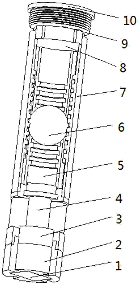
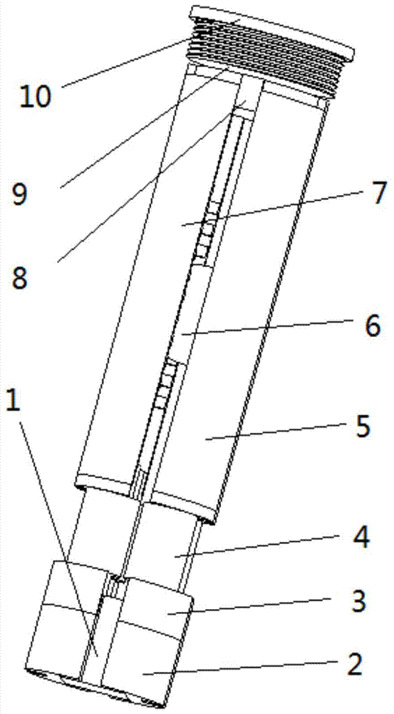
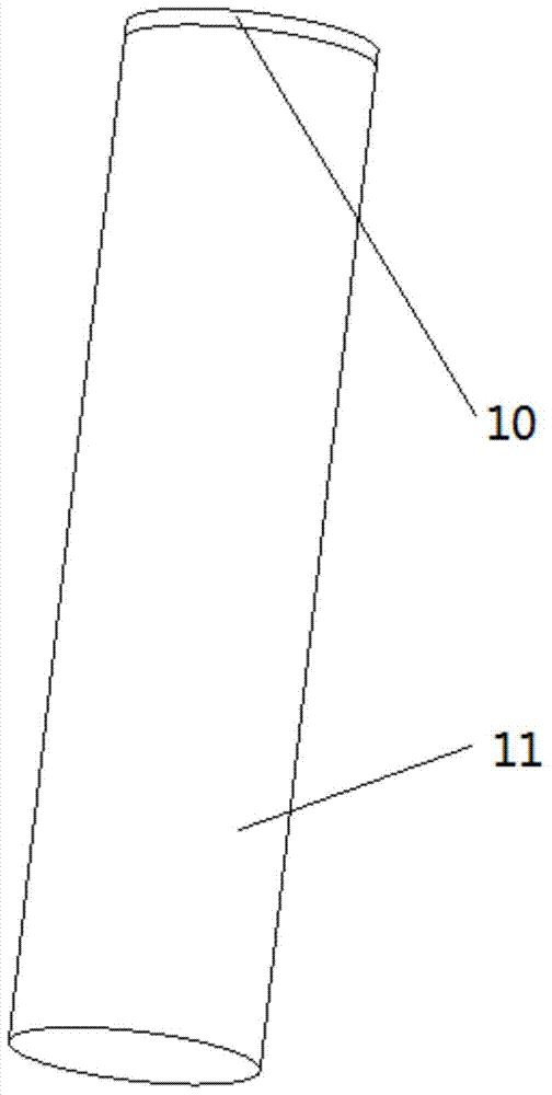
[0027] Reference Figure 1 ~ Figure 7 , A rolling vibrator linear vibration energy harvesting device, comprising a housing 11, the energy harvesting device further comprising a permanent magnet 1, a bottom yoke 2, a coil support 3, a front and rear yoke 5, and a left and right yoke 7 located in the housing;

[0028] The permanent magnet 1 has N poles and S poles. There are two bottom yokes 2 on the permanent magnet 1. Each bottom yoke 2 has two coil bases on which coil supports are placed. Two coil supports 3, the bottom yoke corresponding to the N pole is used to place the left coil support and the rear coil support, the bottom yoke corresponding to the S pole is used to place the right coil support and the front coil support, the four coil supports 3 are identical;

[0029] The induction coil 4 is wound on the coil support 3, and the induction coils on each coil support are connected i...


PUM


Abstract

A rolling vibrator linear vibration energy collection device. There are two bottom yokes on the permanent magnet. Each bottom yoke has two coil bases for placing coil supports. Four coil supports are placed on the coil bases. The bottom corresponding to the N pole is The yoke is used to place the left coil support and the rear coil support, and the bottom yoke corresponding to the S pole is used to place the right coil support and the front coil support. The four coil supports are identical; The induction coils are connected in series, and the four coil supports are equipped with a yoke base for placing four yokes. Each yoke has teeth, and the width of the bottom of the tooth is the same as that of the top of the tooth. The left and right yokes are the same as the front and rear. The teeth on the yoke are distributed in a staggered manner; spherical vibrators are arranged in the cavity surrounded by the front and rear yokes and the left and right yokes, and the top of each yoke is connected with the yoke bracket. The invention provides a rolling vibrator linear vibration energy collection device with less magnetic flux leakage, higher energy conversion rate, small friction coefficient and good stability.

Description

Technical field [0001] The invention relates to an energy harvesting device, in particular to an electromagnetic vibration energy harvesting device. Background technique [0002] Power supply for wireless sensor networks or distributed small systems is a difficult point. Vibration is a form of energy in nature. For example, the waves on the sea surface, the swinging of branches under the wind, and bumpy vehicles. Vibration power generation converts the energy generated by various vibrations into electrical energy. It is a potential new power generation device that is pollution-free and does not consume natural resources. It is suitable for wireless sensor networks or distributed small system nodes. [0003] One way to realize vibration power generation is electromagnetic induction phenomenon power generation. Conventional electromagnetic induction vibration power generation devices have different internal structures. The vibration generator with the application number 200410067...

Claims


Application Information

Patent Timeline
Patent Type & Authority Patents(China)
IPC IPC(8): H02K35/02
Inventor 张端王满州
Owner ZHEJIANG UNIV OF TECH
Why Eureka
Try Eureka