Current transformers and load interrupters having such current transformers

A technology of current transformers and transformers, applied in inductors, voltage/current isolation, instruments, etc., can solve the problem of impossible to monitor multiple parameters at the same time

Active Publication Date: 2019-02-26
EFEN
View PDF6 Cites 0 Cited by
  • Summary
  • Abstract
  • Description
  • Claims
  • Application Information

AI Technical Summary

Problems solved by technology

Known structures also only allow display of a single parameter such as detected current intensity
The display of other parameters is either not possible or can only be used as a substitute, making it impossible to monitor multiple parameters simultaneously

Method used


Image

  • Current transformers and load interrupters having such current transformers
  • Current transformers and load interrupters having such current transformers
  • Current transformers and load interrupters having such current transformers

Examples


Embodiment Construction

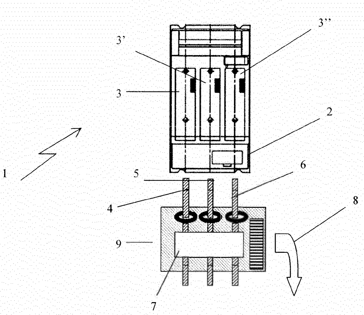
[0026] figure 1 A schematic diagram of an NH fuse switch circuit breaker 1 is shown. It has a housing 2 in which three fuse inserts 3, 3' and 3" are arranged. On its underside, three output connections 4, 5, 6 and a current transformer block 9, the current transformer The block 9 is fixed to the underside of the circuit breaker in such a way that the output connection extends through the circuit breaker. The current transformer system 9 has a connection 8 through which the transformer system can be connected to a bus system, i.e. a data transmission system The embodiment also has a display device 7 capable of displaying the determined parameters.

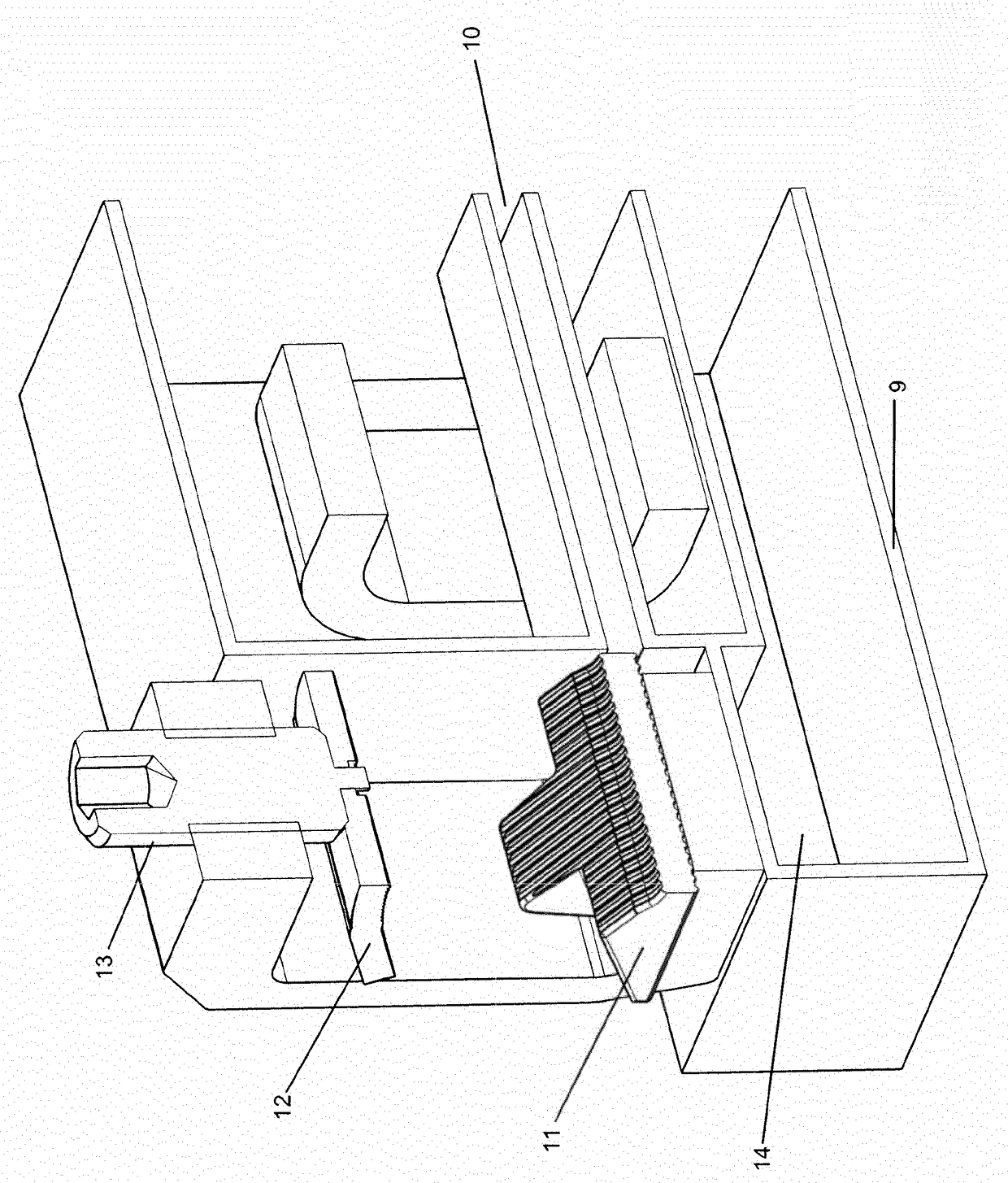
[0027] figure 2 show figure 1 Cutaway view of the current transformer system. The housing 2 has a through hole 10 for receiving a corresponding output connection. also, figure 2 The output terminals 11 , 12 are shown, the lower part 11 of which is in electrical contact with the output connection inserted into the through-hol...


PUM


Abstract

The present invention relates to a current transformer system having a current transformer, which detects a current flowing through the current transformer and converts said current into a measurement voltage, and evaluation electronics which, on the basis of the measurement voltage, determine at least one of the characteristic variables from the group G consisting of I, In, Ist, Imin, ITR, IMAX, U, Un, f, fn, PF, where I = electrical current flowing through the current transformer; In = stated reference current intensity for which the current transformer has been designed; Ist = lowest stated value of I at which the current transformer measures electrical active energy with a power factor of one; Imin = value of I above which the deviation is within the error limits; ITR = value of I above which the deviation is within the lowest error limits corresponding to the accuracy class stated for the current transformer system; IMAX = maximum value of I at which the deviation is within the error limits; U = electrical voltage applied to the current transformer; Un = stated reference voltage; f = frequency of the voltage applied to the current transformer; fn = stated reference frequency; PF = power factor = cos&phgr; = cosine of the phase shift &phgr; between I and U.

Description

technical field [0001] The invention relates to an NH fuse-switch circuit breaker or an NH fuse-switch rail having a housing with a bottom side and at least one feed connection and at least one outlet connection. Background technique [0002] Such voltage high power (NH) fuse switch circuit breakers or NH fuse switch rails are well known and used to provide safety egress for busbars which can be separated under load. The device typically has one or more lower fuse components disposed in the housing. Corresponding fuse inserts are mounted, for example, on the switch cover such that when the switch cover is closed, the fuse insert fits into the lower fuse part and connects the corresponding feed-in connections, which can be connected to the busbar, with the output connections. When the switch cover is opened, the fuse insert is pulled out from the lower fuse part, causing the connection to be interrupted. [0003] In principle, the invention can also be used in connection wi...

Claims


Application Information

Patent Timeline
Patent Type & Authority Patents(China)
IPC IPC(8): G01R15/14G01R15/18H01F38/32H01H85/30
CPCG01R15/183G01R15/142H01F38/32H01H31/122
Inventor M·施罗德L·桑德哈格
Owner EFEN
Why Eureka
Try Eureka