Turbine engine cowl capable of covering a fan cone

A technology of turbine engine and cone, which is applied in the direction of machines/engines, engine components, engine functions, etc. It can solve the problems of reducing aerodynamics and achieve the effect of simplifying processing

Active Publication Date: 2015-08-26
SN DETUDE & DE CONSTR DE MOTEURS DAVIATION S N E C M A
View PDF3 Cites 1 Cited by
  • Summary
  • Abstract
  • Description
  • Claims
  • Application Information

AI Technical Summary

Problems solved by technology

[0006] The attachment holes 11, the removal holes 12 and the holes for the balancing screws 13 are all geometric discontinuities on the upstream side of the fan that cause flow disturbances and reduce the aerodynamics of the system

Method used


Image

  • Turbine engine cowl capable of covering a fan cone
  • Turbine engine cowl capable of covering a fan cone
  • Turbine engine cowl capable of covering a fan cone

Examples


Embodiment Construction

[0046] Any element appearing in different figures will have a reference number unless otherwise specified.

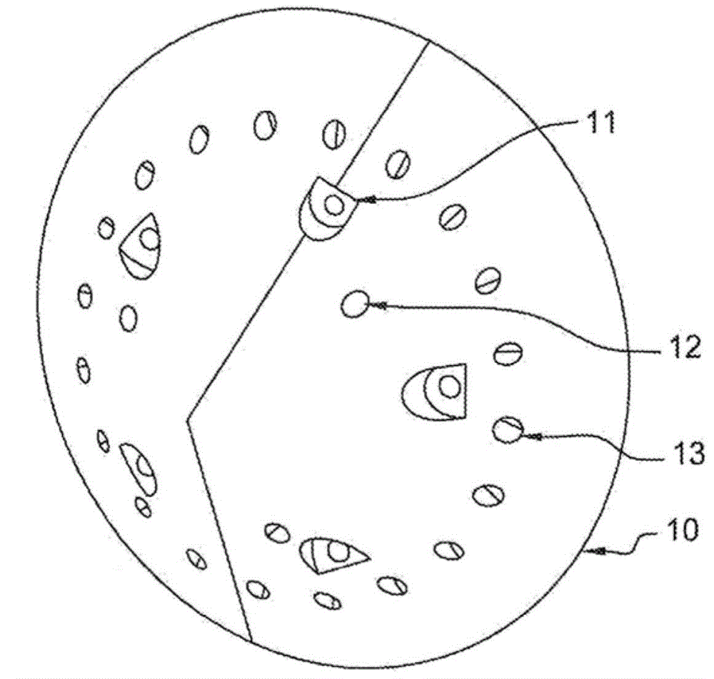
[0047] The invention makes it possible to eliminate aerodynamic disturbances to the airflow in the fan cone due to geometrical discontinuities on the outer surface of said cone caused by the different holes mentioned above. This is achieved by placing the hood over the cone. Both the cowl and the cone are provided with means for engaging each other to secure themselves to each other.

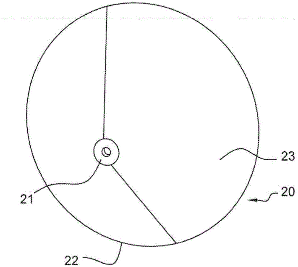
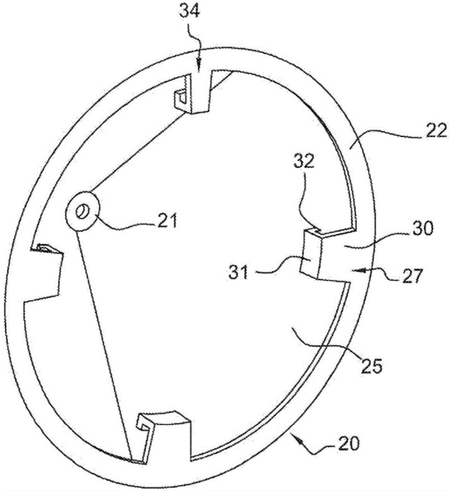
[0048] figure 2 and image 3 A hood 20 according to one non-limiting example of the invention is schematically shown. figure 2 shows an upstream view of the hood 20, while image 3 A downstream view thereof is shown. The terms "upstream" and "downstream" should be considered with respect to the usual direction of gas flow on the cowl 20, with gas flowing in a direction from the upstream side to the downstream side, when the cowl is mounted on the fan cone. The shroud 20 has an ove...


PUM


Abstract

The invention relates to a turbine engine cowl (20) capable of covering a fan cone (24), characterised in that said cowl comprises attachment means (27, 32, 36) capable of engaging with connection means (28, 33, 39) of said cone (24) in order to maintain said cowl (20) and said cone (24) secured to one another.

Description

technical field [0001] The invention relates to the field of turbine engines, in particular of aircraft, preferably of the turbofan type. More specifically, the invention relates to a turbojet fan cone. Background technique [0002] A turbojet engine comprising, on its upstream side, an air intake feeding a fan and a compressor, the blades of which are supported on disks fixed to a shaft extending over a substantial part of the turbojet engine and by the The turbine of the turbojet engine is driven in rotation. It is to be noted that the terms "upstream" and "downstream" should be considered from the upstream side to the downstream side with respect to the usual direction of fluid flow through the turbojet engine. [0003] An intake cone is mounted upstream of the shaft to deflect a portion of the airflow entering the turbojet towards the fan blades, which flow is then divided into the core engine flow, which flows into the inlet of the compressor, and the fan flow, which ...

Claims


Application Information

Patent Timeline
Patent Type & Authority Applications(China)
IPC IPC(8): F02K3/06B64C11/14F02C7/04
CPCF05D2260/33F05D2220/36F02C7/04F02K3/06Y02T50/60B64C11/14
Inventor 达米恩·墨尔乐
Owner SN DETUDE & DE CONSTR DE MOTEURS DAVIATION S N E C M A
Why Eureka
Try Eureka