Driving method and system for stepping motor of digital instrument
A technology of stepping motors and digital instruments, applied in the direction of electrical components, electric pulse generation, pulse generation, etc., can solve the problem of not being able to determine the running process of the motor in real time, and achieve the effect of ensuring accuracy
- Summary
- Abstract
- Description
- Claims
- Application Information
AI Technical Summary
Problems solved by technology
Method used
Image
Examples
Embodiment 1
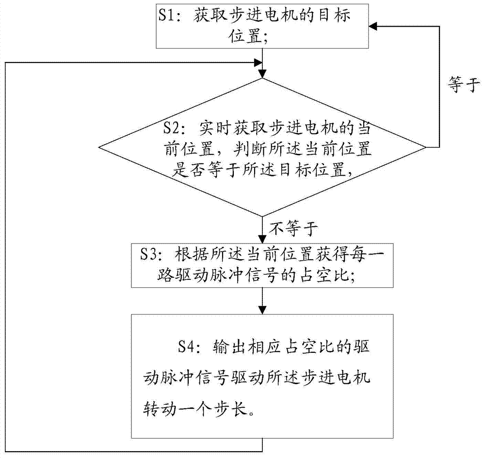
[0049] This embodiment provides a driving method for a stepping motor of a digital instrument, see figure 1 shown, including the following steps:
[0050] S1: Obtain the target position of the stepper motor.
[0051] S2: Acquiring the current position of the stepping motor in real time, judging whether the current position is equal to the target position, and returning to step S1 if they are equal, otherwise entering step S3.
[0052] S3: Obtain the duty cycle of each drive pulse signal according to the current position.
[0053] S4: Outputting a driving pulse signal with a corresponding duty ratio to drive the stepping motor to rotate for one step, and then return to the step S2.
[0054] In the driving method of the digital instrument stepper motor in this embodiment, the current position and the target position of the stepper motor are determined by obtaining the operating state of the motor in real time in the control flow, and comparing the current position with the targe...
Embodiment 2
[0077] This embodiment provides a driving system for a digital instrument stepper motor, such as Figure 4 As shown, it includes a first data acquisition module, a second data acquisition module, a data processing module and a drive signal output module. in:
[0078] The first data acquisition module is used to acquire the target position of the stepping motor. The second data acquisition module is used for acquiring the current position of the stepper motor in real time, and judging whether the current position is equal to the target position. The data processing module is used for not needing to drive the stepper motor when the current position is equal to the target position, otherwise, the duty ratio of each drive pulse signal is obtained according to the current position. The driving signal output module is used to output a driving pulse signal corresponding to a duty ratio to drive the stepping motor to rotate until the current position of the motor is equal to the tar...
Embodiment 3
[0084] This embodiment provides a method for driving a stepping motor by using a central processing unit in a digital instrument. The central processing unit uses the driving method for a stepping motor of a digital instrument described in Embodiment 1 to output a driving pulse signal to drive the stepping motor. Wherein said central processing unit is MC9S12H256 chip, and it has 24 PWM output ports, wherein 4 PWM output ports are connected with the voltage input end of the stator magnetic field coil of a stepper motor to be driven as the output end of drive pulse signal, this It can drive 6 stepping motors at the same time, which can well meet the number of motors that need to be driven on the pointer instrument panel in the digital instrument.
[0085] Such as Figure 5 A schematic diagram of the circuit connection between the MC9S12H256 chip and the stepping motor is given.
[0086] Figure 5 The shown M0C0M / PUO, M0C0P / PU1, M0C1M / PU2, M0C1P / PU3 are the first group, which ...
PUM
 Abstract
Description
Claims
Application Information
 - R&D
- Intellectual Property
- Life Sciences
- Materials
- Tech Scout
- Unparalleled Data Quality
- Higher Quality Content
- 60% Fewer Hallucinations
Browse by: Latest US Patents, China's latest patents, Technical Efficacy Thesaurus, Application Domain, Technology Topic, Popular Technical Reports.
© 2025 PatSnap. All rights reserved.Legal|Privacy policy|Modern Slavery Act Transparency Statement|Sitemap|About US| Contact US: help@patsnap.com


