
Multilayer antenna structure and antenna

A multi-layer antenna and lower-layer technology, which is applied in the direction of antenna grounding switch structure connection, antenna, antenna grounding device, etc., can solve the problem that the antenna cannot meet the performance and thickness requirements

Active Publication Date: 2015-08-26
BAICELLS TECH CO LTD
View PDF2 Cites 3 Cited by
  • Summary
  • Abstract
  • Description
  • Claims
  • Application Information

AI Technical Summary

Problems solved by technology

[0005] Embodiments of the present invention provide a multi-layer antenna structure and antenna to at least solve the technical problem that the antenna cannot meet the performance and thickness requirements

Method used


Image

  • Multilayer antenna structure and antenna
  • Multilayer antenna structure and antenna
  • Multilayer antenna structure and antenna

Examples


Embodiment Construction

[0027] In order to enable those skilled in the art to better understand the solutions of the present invention, the following will clearly and completely describe the technical solutions in the embodiments of the present invention in conjunction with the drawings in the embodiments of the present invention. Obviously, the described embodiments are only It is an embodiment of a part of the present invention, but not all embodiments. Based on the embodiments of the present invention, all other embodiments obtained by persons of ordinary skill in the art without making creative efforts shall fall within the protection scope of the present invention.

[0028] It should be noted that the terms "first" and "second" in the description and claims of the present invention and the above drawings are used to distinguish similar objects, but not necessarily used to describe a specific sequence or sequence. It is to be understood that the data so used are interchangeable under appropriate ...


PUM

PropertyMeasurementUnit
Thicknessaaaaaaaaaa
Thicknessaaaaaaaaaa

Abstract

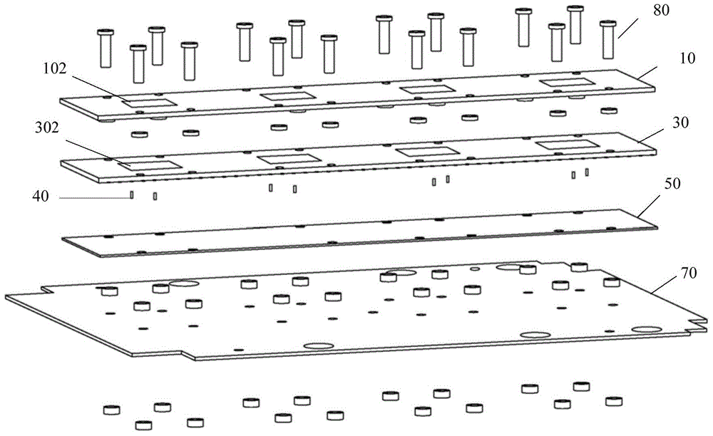
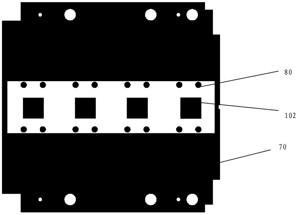
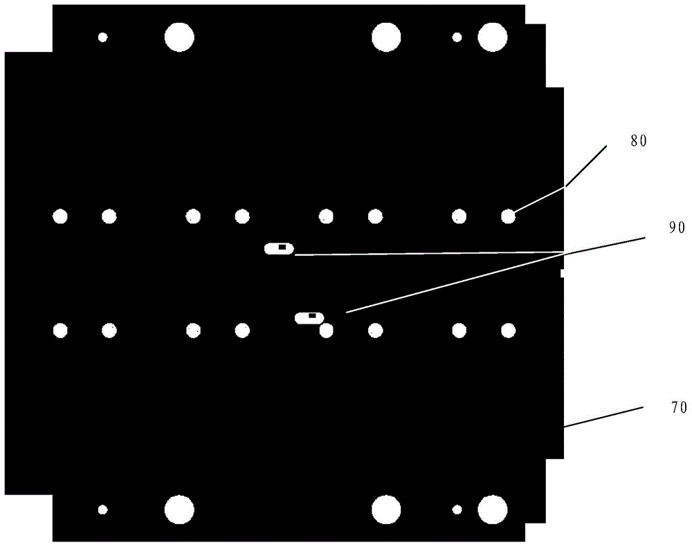
The invention discloses a multilayer antenna structure and an antenna. The multilayer antenna structure comprises an upper layer dielectric substrate, a middle layer dielectric substrate, a lower layer dielectric substrate and a reflection plate which are sequentially arranged, wherein the upper surface of the upper layer dielectric substrate is provided with parasitic patches; the middle layer dielectric substrate and the upper layer dielectric substrate are arranged at an interval, the upper surface of the middle layer dielectric substrate is provided with radiation patches, and the lower surface of the middle layer dielectric substrate is integrally attached with a first metal grounding layer; the upper surface of the lower layer dielectric substrate is arranged in a mode of clinging to the lower surface of the middle layer dielectric substrate, the lower surface of the lower layer dielectric substrate is provided with a feed structure, the upper surface of the lower layer dielectric substrate is integrally attached with a second metal grounding layer, and the feed structure and the radiation patches are connected through metal probes; and the reflection plate is located at the lower surface side of the lower layer dielectric substrate, and an interval of the reflection plate and the lower layer dielectric substrate is provided with an air layer. The multilayer antenna structure disclosed by the invention solves a technical problem that the antenna cannot give consideration to both performance and thickness requirements.

Description

technical field [0001] The present invention relates to the field of antennas, in particular to a multilayer antenna structure and antenna. Background technique [0002] In various wireless devices, the antenna is a very important component, and its main function is to transmit and receive wireless signals. With the continuous development of antenna technology, there are higher requirements for the radiation performance, reception performance and aesthetics of the antenna itself. [0003] The 5GHz frequency band is an internationally common license-free frequency band. There are a large number of wireless devices in this frequency band. Due to the size limitation of various wireless devices, the size of the antenna needs to be further compressed, and at the same time, it is necessary to ensure a good antenna performance. However, when the thickness of the existing antenna is relatively thin, it cannot achieve better antenna performance (such as relative bandwidth, etc.); w...

Claims


Application Information

Patent Timeline
IPC IPC(8): H01Q1/38H01Q1/50H01Q19/10H01Q1/48
Inventor 白炜刘建江刘艳明
Owner BAICELLS TECH CO LTD
Learn More