
Soot measurement system and soot measurement method by extinction method with pre-positioned light source

A measurement system and extinction method technology, applied in the direction of measurement device, transmittance measurement, scattering characteristic measurement, etc., can solve the problems of limited incident light absorption ability, large experimental error, and limited application

Inactive Publication Date: 2015-08-26
JILIN UNIV
View PDF5 Cites 3 Cited by
  • Summary
  • Abstract
  • Description
  • Claims
  • Application Information

AI Technical Summary

Problems solved by technology

The light source rear extinction method requires two optical windows, and the light source and camera must be arranged horizontally on both sides of the soot area, which limits the application of this method on traditional diesel engines
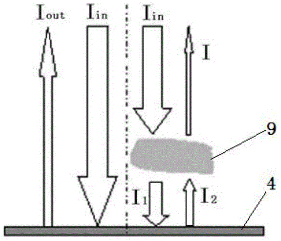
In addition, the laser light source enters the collection equipment after passing through the soot area once, which is more suitable for heavy soot conditions, but for clean fuels such as biodiesel and alcohol fuels, or light soot conditions such as low-load and low-temperature combustion, due to soot The generated mass itself is small, and the ability to absorb incident light is limited. The difference between the light intensity entering the collection device and the incident light is small, so the experimental error is large

Method used


Image

  • Soot measurement system and soot measurement method by extinction method with pre-positioned light source
  • Soot measurement system and soot measurement method by extinction method with pre-positioned light source
  • Soot measurement system and soot measurement method by extinction method with pre-positioned light source

Examples


Embodiment Construction

[0037] The structure and working principle of a soot measurement system with extinction method in front of the light source will be further described below in conjunction with the accompanying drawings.

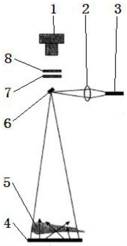
[0038]The measurement scheme is composed of high-speed camera 1, ND light reduction lens 7, interference filter lens 8, reflector 6, laser light source 3, lens 2 and light scattering disc 4; its relative arrangement position is: interference filter lens 8 and ND The light reduction lens 7 forms an optical window and is sequentially placed on the lens front end of the high-speed camera 1, the reflector 6 is placed directly in front of the ND light reduction lens 7 at an angle of 45°, the laser light source 3 is placed in the horizontal incident angle direction of the reflector 6, and the lens 2 is placed between the laser light source 3 and the reflector 6, and the light scattering disc 4 is fixed on the bottom of the burning oil beam 5 in the direction of the vertical reflecti...


PUM

PropertyMeasurementUnit
diameteraaaaaaaaaa

Abstract

The invention relates to a soot measurement system and a soot measurement method by an extinction method with a pre-positioned light source, belonging to the technical field of internal combustion engines. An interference filter lens and an ND light-reducing lens in the soot measurement system by the extinction method with the pre-positioned light source are sequentially arranged at the front end of a lens of a high-speed camera, a reflector is arranged right ahead the ND light-reducing lens at an angle of 45 degrees, a laser light source is arranged in a horizontal incident direction of the reflector, an optical lens is arranged between the laser light source and the reflector, and a light scattering disc is fixedly arranged at the bottom of a combustion oil pocket in the vertical reflective angle direction of the reflector. By using the unique structure of the soot measurement system by the extinction method with the pre-positioned light source, soot in a combustor can be measured, particularly soot of clean fuels such as conventional diesel engines, biodiesel, alcohol fuels and the like or light soot working conditions such as low loads, low-temperature combustion and the like, so that the deficiency that the extinction method with a post-positioned light source can be compensated.

Description

technical field [0001] The invention belongs to the technical field of internal combustion engines, and in particular relates to a extinction method using a light source in front to realize the quantitative measurement and generation law research of different engine loads and different types of fuel soot over time. Background technique [0002] With the increasingly stringent exhaust emission regulations, pure off-board purification technology is difficult to meet the needs, so higher requirements are put forward for the in-cylinder fuel spray and combustion process. The application of laser testing and high-speed imaging technology makes it possible to observe the movement and combustion changes of fuel in the cylinder. The continuous and clear visualization results can enable people to further understand the complete process of fuel from injection evaporation, ignition and combustion to emission generation in high-temperature and high-pressure environments. The process pla...

Claims


Application Information

Patent Timeline
Patent Type & Authority Applications(China)
IPC IPC(8): G01N15/02G01N15/06G01N21/01G01N21/61G01N21/49
Inventor 刘宇李君徐潘龙乔世杰王亚
Owner JILIN UNIV
Learn More