A method and evaluation device for evaluating strike capability, and proofreading of the evaluation device
A striking force and ability technology, applied in measuring devices, calibration/testing of force/torque/power measuring instruments, force/torque/power measuring instruments, etc., can solve problems such as evaluation, failure to give strikes, incomparability, etc. , to achieve the effect of reducing mechanical energy loss, saving costs and facilitating installation
- Summary
- Abstract
- Description
- Claims
- Application Information
AI Technical Summary
Problems solved by technology
Method used
Image
Examples
no. 1 example
[0050] The first embodiment, the evaluation method embodiment, is described in detail as follows:
[0051] The impact object acts on the elastic device, causing the elastic device to deform, and if there is power, the power will do work in the process. The greater the deformation of the elastic device, the greater the elastic force generated, and finally the striking object reaches the maximum displacement, the elastic device produces the maximum deformation, and the initial kinetic energy and dynamic work of the striking object are all converted into the elastic potential energy of the elastic device. The maximum deformation is the striking effect, and the elastic force produced by the corresponding elastic device is the actual striking force.
[0052]However, it is unscientific to evaluate the actual impact force, because when different elastic devices have different elastic force and deformation relationships, the impacts with the same dynamic force and the same initial kin...
no. 2 example
[0080] The second embodiment, embodiment 1 of the evaluation device, is described in detail as follows:
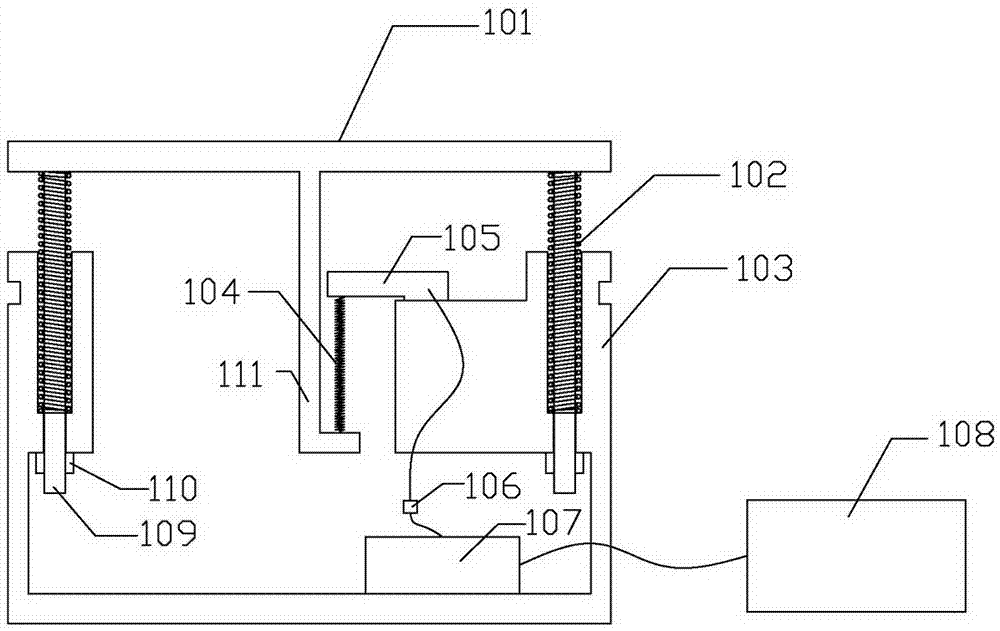
[0081] figure 1 A schematic structural view of the evaluation device provided by the second embodiment of the present invention is shown, specifically as follows:
[0082] The impact receptor 101 is connected to an elastic buffer device 102 , and the elastic buffer device 102 is connected to a structural support device 103 . The impact receptor 101 is equipped with a limit rod 109, and the limit rod 109 first functions to limit the movement of the impact receptor 101 in the horizontal direction as shown. The limit rod 109 is provided with a lock nut 110 at the lower end shown in the figure, and the lock nut 110 can adjust and lock the distance between it and the end point of the limit rod 109 , so as to adjust and lock the preload of the elastic buffer device 102 .
[0083] In this embodiment, the elastic buffer device 102 is composed of a number of uniformly distributed...
no. 3 example
[0104] The third embodiment, embodiment 2 of the evaluation device, is described in detail as follows:
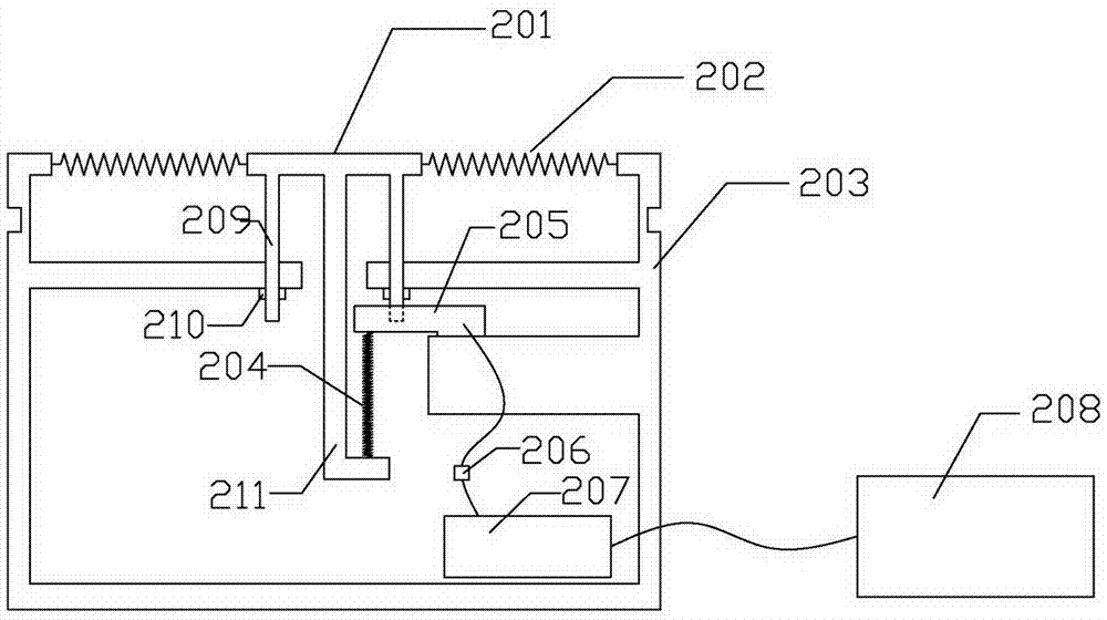
[0105] figure 2 A schematic structural diagram of the evaluation device provided by the third embodiment of the present invention is shown, specifically as follows:
[0106] The impact receptor 201 is connected to an elastic buffer device 202 , and the elastic buffer device 202 is connected to a structural support device 203 . The impact receptor 201 is equipped with a limit rod 209, and the limit rod 209 first plays the role of strengthening and restricting the movement of the impact receptor 201 in the horizontal direction as shown. The limit rod 209 is provided with a lock nut 210 at the lower end as shown in the figure, and the lock nut 210 can adjust and lock the distance between it and the end point of the limit rod 209 , so as to adjust and lock the preload of the elastic buffer device 202 .
[0107] In this embodiment, the elastic buffer device 202 is composed of...
PUM
 Abstract
Description
Claims
Application Information
 - R&D
- Intellectual Property
- Life Sciences
- Materials
- Tech Scout
- Unparalleled Data Quality
- Higher Quality Content
- 60% Fewer Hallucinations
Browse by: Latest US Patents, China's latest patents, Technical Efficacy Thesaurus, Application Domain, Technology Topic, Popular Technical Reports.
© 2025 PatSnap. All rights reserved.Legal|Privacy policy|Modern Slavery Act Transparency Statement|Sitemap|About US| Contact US: help@patsnap.com


