
Concrete diaphragm wall lateral earth pressure cell embedding device

A technology of earth pressure box and ground connection wall, which is applied in the field of foundation soil survey, construction, infrastructure engineering, etc., can solve the problems of complex operation and limited jacking force, and achieve simple operation, low installation cost, regularity and good correlation effect

Inactive Publication Date: 2015-08-26
HOHAI UNIV
View PDF2 Cites 12 Cited by
  • Summary
  • Abstract
  • Description
  • Claims
  • Application Information

AI Technical Summary

Problems solved by technology

This method is complicated to operate, and the jacking force provided by the pneumatic parts is limited

Method used


Image

  • Concrete diaphragm wall lateral earth pressure cell embedding device
  • Concrete diaphragm wall lateral earth pressure cell embedding device
  • Concrete diaphragm wall lateral earth pressure cell embedding device

Examples


Embodiment Construction

[0037] The present invention will be described in further detail below in conjunction with the accompanying drawings.

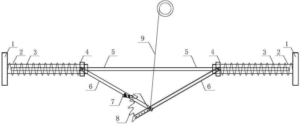
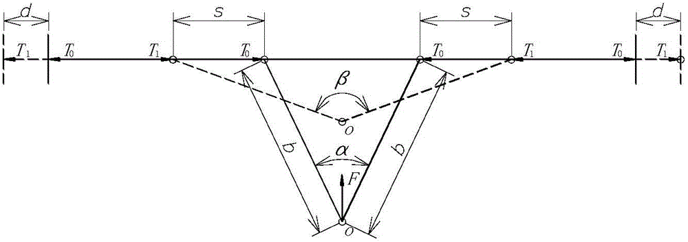
[0038] 1. attached figure 1 And attached figure 2It can be seen that the earth pressure box embedding device on the side of the wall of the present invention is characterized in that it includes an earth pressure box base 1, a sleeve 2, a spring 3, a circular slider 4, a steel guide rod 5, a strut 6, a locking Block 7, toothed block 8 and pull wire 9; the calibrated earth pressure box is fixed on the base 1 of the earth pressure box through positioning screws, the sleeve 2 is welded vertically to the center of the base 1 of the earth pressure box, the compression spring 3 and the circular slider 4. The inner diameter is slightly larger than the outer diameter of the sleeve 2, which can be just placed on the sleeve 2. The inner diameter of the sleeve 2 is slightly larger than the steel guide rod 5, which can be just placed on it and can slide freely. The st...


PUM


Abstract

The invention discloses a concrete diaphragm wall lateral earth pressure cell embedding device, and relates to an application technology for monitoring concrete diaphragm wall lateral earth pressure in a water control project risk assessment and control process. The concrete diaphragm wall lateral earth pressure cell embedding device comprises a steel guide rod, sleeves for being connected with earth pressure cell bases, and support rods; the sleeves (2) for being connected with the earth pressure cell bases can freely slide on the steel guide rod (5); when a guy wire (9) is tensioned, the support rods (6) push circular sliding blocks (4) sleeving the sleeves (2) to compress springs (3), the springs (3) push the earth pressure cell bases (1) and the sleeves (2) to be supported into concrete diaphragm wall lateral earth; a tooth-shaped block (8) and a locking block (7) at the tail ends of the support rods (6) form a graded locking device allowing the support rods (6) to be locked at different angles, so that requirements of different concrete diaphragm wall widths and hardness and softness of earth on two sides of the wall can be met. The concrete diaphragm wall lateral earth pressure cell embedding device can be widely used for embedding an earth pressure cell for monitoring lateral earth pressure of various cast-in-situ concrete diaphragm walls in a water control project.

Description

technical field [0001] The present invention relates to an application technology of earth pressure cell when monitoring earth pressure in water conservancy project risk assessment and control, in particular, relates to an earth pressure cell embedding device, which is mainly used in ship locks and wharfs of earth-connecting wall retaining structures and deep foundation pits. Background technique [0002] With the maturity of the underground continuous sheet pile wall (sheet pile wall) construction technology, more and more water conservancy projects (sluices, pump stations and ship locks, etc.) and water transportation and shipbuilding projects (wharfs, docks) have adopted this structural form. , such as Suining Second Station of the South-to-North Water Diversion Project, Rongsheng Heavy Industry No. 1-4 Dock, China Railway Baoqiao, Shanqiao Harbor Pool Wharf and the completed second-line ship lock of Gaogang Hub, etc., the sheet pile wall can not only achieve temporary ma...

Claims


Application Information

Patent Timeline
Patent Type & Authority Applications(China)
IPC IPC(8): E02D1/00
CPCE02D1/00
Inventor 孙立国杜成斌陈玉泉江守燕顾明如
Owner HOHAI UNIV
Learn More