
Lifting device

A technology of suspension device and reduction device, which is applied in the direction of hoisting device, transportation and packaging, load hanging components, etc., can solve the problems of increasing the volume of the reduction box, easily damaged equipment, occupying space, etc., and achieve the improvement of low speed ratio and reduction failure, the effect of ensuring stability

Active Publication Date: 2015-08-26
JIASHAN THREE STAR BEARING
View PDF5 Cites 0 Cited by
  • Summary
  • Abstract
  • Description
  • Claims
  • Application Information

AI Technical Summary

Problems solved by technology

[0002] The lifting device is a device used to lift objects. It is a large-scale mechanical equipment that is transported by changing the potential energy. The lifting capacity and strength of the lifting device require the support of the bracket and the cooperation of the driving device. The driving device mainly includes a winch and a reduction box. Therefore, the winch and The reduction box plays a very important role; the reduction gear used in the existing reduction box often adopts the ability of the bevel gear to change the direction of the output torque, but the bevel gear is generally located at the shaft head of the rotating shaft, or is installed on the rotating shaft or will The shaft is directly processed into a bevel gear. When the two bevel gears mesh, they will occupy the space other than the rotating shaft, which will increase the volume of the reduction box. After the equipment has been used for a long time, when the oil leaks from the reduction box, it is only found that there is a lack of oil. Add, without adding money, the equipment may work for a long time under the condition of insufficient oil, and the equipment is easy to be damaged after a long time; hoist, light and small lifting equipment that uses a drum to wind a wire rope or chain to lift or pull heavy objects, also known as Winch and hoist can lift heavy objects vertically, horizontally or obliquely. The hoist is divided into two types: manual hoist and electric hoist. Now the electric hoist is the main one. It can be used alone or as machinery for lifting, road construction and mine hoisting. The components in the hoist are widely used because of simple operation, large amount of rope winding, and convenient displacement. They are mainly used for material lifting or flat dragging in construction, water conservancy projects, forestry, mines, docks, etc.; however, many hoists are not equipped with control circuits. It is convenient for manual operation. When a failure occurs in a certain link, it needs to be checked one by one, which is time-consuming and laborious; the suspension device is used to hang the price through the hook. The suspension device is widely used. In industrial production, such as in the lifting mechanism, it is necessary to use the suspension The device can control the hook through the equipment control suspension device, which can hang and put down objects conveniently, eliminating manual operation, which not only improves work efficiency, but also reduces safety problems caused by improper manual operation; however, in practical applications, In particular, the hanging and putting down of large objects still requires manual participation, especially in industrial smelting production, when objects with a high surface temperature are hung on the hook, molten iron is easy to splash and burn the staff, causing personal safety problems.

Method used


Image

  • Lifting device
  • Lifting device
  • Lifting device

Examples


Embodiment Construction

[0026] In order to make the technical means, creative features, goals and effects achieved by the present invention easy to understand, the present invention will be further elaborated below in conjunction with illustrations and specific embodiments.

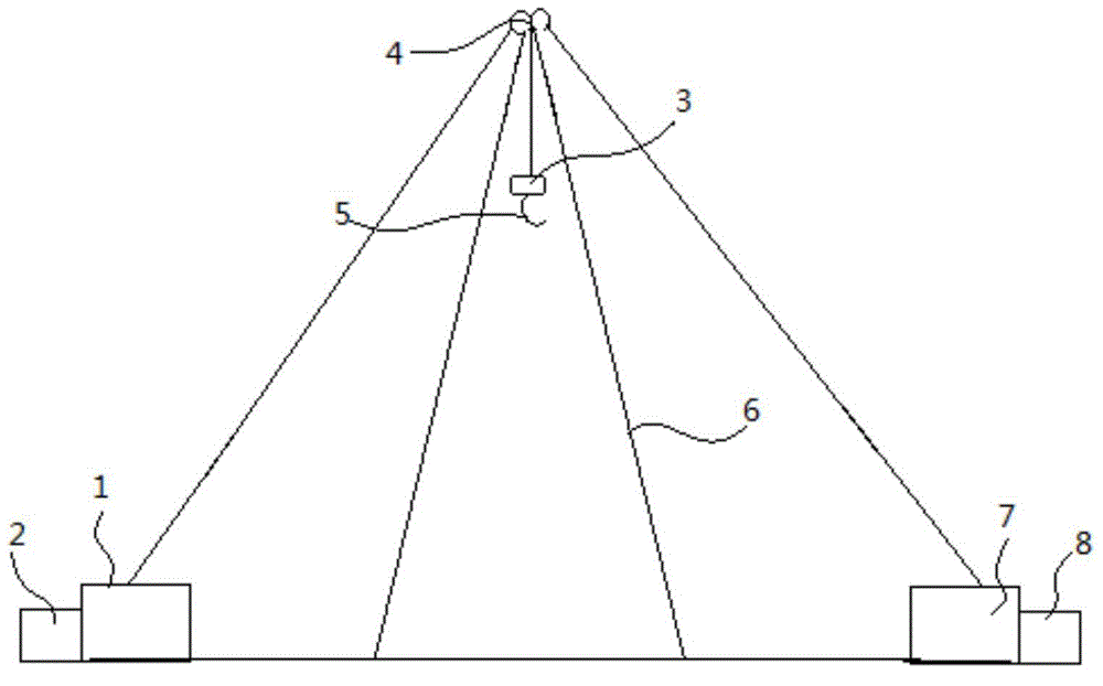
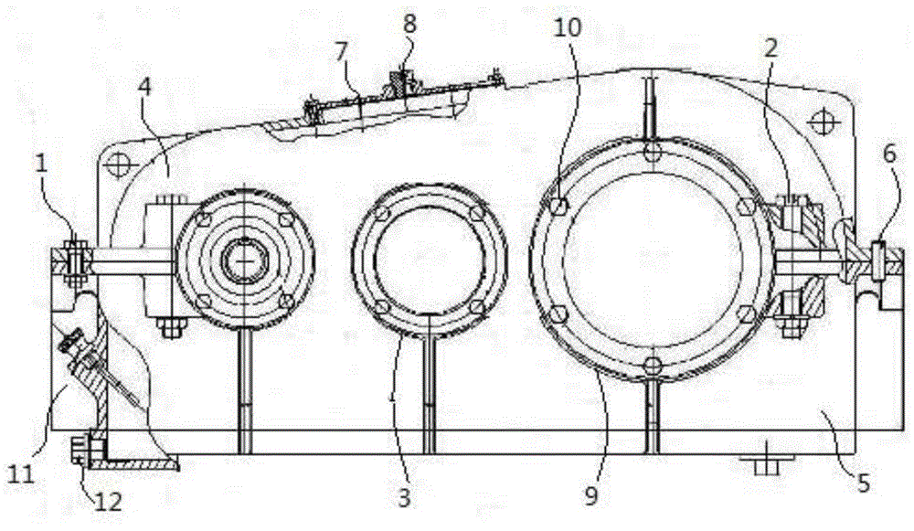
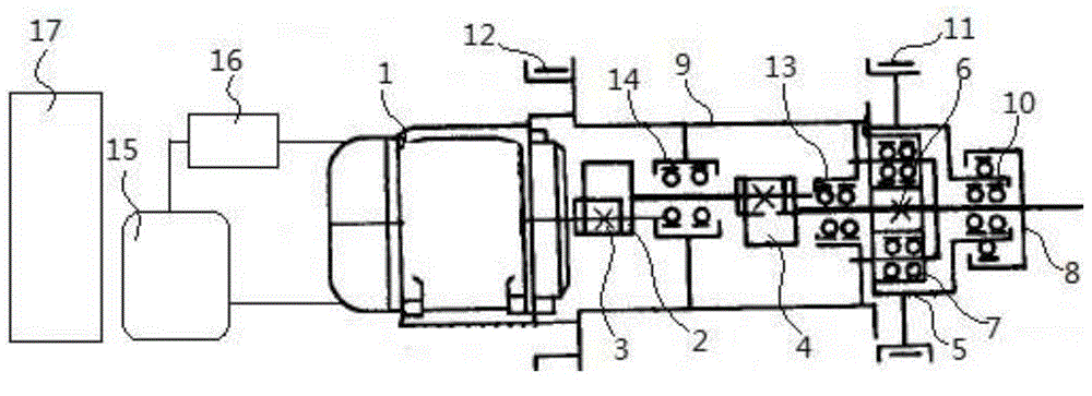
[0027] refer to figure 1 , figure 2 , image 3 , Figure 4As shown, the lifting device includes a first reduction box 1, a first winch 2, a suspension device 3, a roller 4, a hook 5, a bracket 6, a second reduction box 7 and a second hoist 8; The first gear box 1, the first hoist 2, the second gear box 7 and the second hoist 8 are respectively arranged on the side, the first gear box 1 and the first hoist 2 are connected and located on one side of the bracket 6, the second gear box 7 is connected with the second hoist 8 and is located on the other side of the support 6, the first reduction box 1 and the second reduction box 7 are located on the side close to the support 6, the first hoist 2 and the second hoist 8 are located...


PUM


Abstract

The invention discloses a lifting device. The lifting device comprises a reduction gearbox, a first winch, a suspension device, a roller, a lifting hook, a support, a secondary reduction gearbox and a second winch, wherein the two sides of the bottom end of the support are respectively provided with a first reduction gearbox, a first winch, a second reduction gearbox and a second winch; the top end of the support is provided with the roller, the lower end of the roller is provided with the suspension device, and the lower end of the suspension device is provided with the hook; another side of a hook opening is provided with a fixed ring, the fixed ring is connected with a first idler wheel and a second idler wheel through steel cables, the first idler wheel and the second idler wheel are used cooperatively to drive the lifting hook to rotate at one side deviated from the hook opening under the condition that the hook cannot be taken down, i.e. an article on the hook can be easily dismounted, so that the lifting device is more convenient to operate; furthermore, a control cabinet in the winch is internally provided with a CPU (Central Processing Unit), and a controller is connected with a control loop, so as to detect the power conditions of a main loop and a motor in real time and the connecting condition between the motor and the reduction box, and detect whether a rotor in the motor is in a good condition and the like, therefore the stability of operation can be ensured.

Description

technical field [0001] The invention relates to the field of industrial lifting transmission, in particular to a lifting device. Background technique [0002] The lifting device is a device used to lift objects. It is a large-scale mechanical equipment that is transported by changing the potential energy. The lifting capacity and strength of the lifting device require the support of the bracket and the cooperation of the driving device. The driving device mainly includes a winch and a reduction box. Therefore, the winch and The reduction box plays a very important role; the reduction gear used in the existing reduction box often adopts the ability of the bevel gear to change the direction of the output torque, but the bevel gear is generally located at the shaft head of the rotating shaft, or is installed on the rotating shaft or will The shaft is directly processed into a bevel gear. When the two bevel gears mesh, they will occupy the space other than the rotating shaft, wh...

Claims


Application Information

Patent Timeline
Patent Type & Authority Applications(China)
IPC IPC(8): B66D1/60B66D1/12B66D1/14B66D1/46B66D1/54B66C1/38
CPCB66D1/14B66D1/26B66D1/46B66D1/54
Inventor 钱咬法
Owner JIASHAN THREE STAR BEARING
Learn More