Automatic clamping tool

An automatic clamping and tooling technology, applied in the mechanical field, can solve the problems of difficult quantification of clamping force, excessive clamping force, abnormal processing, etc., to improve efficiency and safety, and ensure the effect of clamping stability.

Inactive Publication Date: 2015-08-26
天津沃尔德泰克机电有限公司
View PDF0 Cites 5 Cited by
  • Summary
  • Abstract
  • Description
  • Claims
  • Application Information

AI Technical Summary

Problems solved by technology

[0003] In view of this, the present invention aims to propose an automatic clamping tool to solve the problem that the clamping force of the manual clamping operation is difficult to quantify, and the clamping force is too large or too small to easily cause abnormal processing

Method used


Image

  • Automatic clamping tool
  • Automatic clamping tool

Examples


Embodiment Construction

[0019] It should be noted that, in the case of no conflict, the embodiments of the present invention and the features in the embodiments can be combined with each other.

[0020] The present invention will be described in detail below with reference to the accompanying drawings and examples.

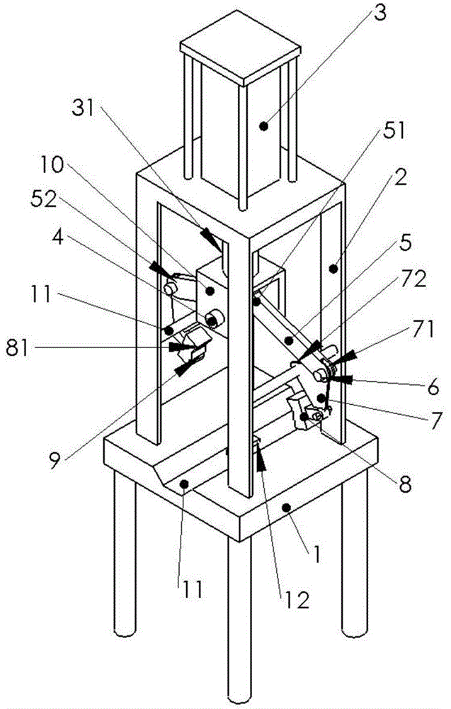
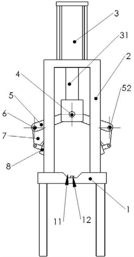
[0021] Such as figure 1 , 2 As shown, an automatic clamping tool, including:

[0022] A workbench 1, the middle part of the workbench 1 is provided with a trapezoidal cross section and a receiving tank 101 horizontally passing through the workbench 1, and a first pressure sensor is arranged in the receiving tank 101, and the first pressure sensor and Controller electrical connection;

[0023] Cylinder 3, the cylinder 3 is fixed on the top of the workbench 1 through the bracket 2, its piston rod 31 faces down and is located directly above the receiving groove 101, and the piston rod 31 is fixedly connected with the connecting frame 10;

[0024] Clamping unit, the clamping unit is hing...


PUM


Abstract

The invention provides an automatic clamping tool. The automatic clamping tool comprises a working table, a cylinder and a clamping unit, wherein a containing groove is formed in the middle of the working table, a first pressure sensor is arranged in the containing groove and electrically connected with a controller, the cylinder is fixed above the working table through a support, a piston rod faces downwards and is located over the containing groove, the piston is fixedly connected with a connecting frame, the clamping unit is hinged to the connecting frame through a first articulated shaft and comprises two sets of first clamping rods and clamping plates which are hinged to each other through second articulated shafts, each clamping plate is in threaded connection with a clamping head which is provided with a second pressure sensor, and the second pressure sensors are electrically connected with the controller. According to the automatic clamping tool, a clamping pressure value is set according to specifications of a workpiece, the clamping stability is guaranteed, and the local crushing phenomenon cannot be caused simultaneously; meanwhile, the efficiency and the safety of the clamping operation can be improved.

Description

technical field [0001] The invention belongs to the field of machinery, and in particular relates to an automatic clamping tool. Background technique [0002] In the field of mechanical processing, when turning a workpiece, in order to overcome the turning force of the turning process on the workpiece and ensure high machining accuracy, it is necessary to perform clamping and positioning operations on the workpiece during the turning process. However, the currently used positioning tooling requires the operator to perform manual clamping operations, and it is difficult to quantify the clamping force on the workpiece. Often, local plastic pits are formed on the surface of the workpiece due to excessive local pressure, and sometimes due to insufficient clamping force As a result, the position of the workpiece changes during the machining process, resulting in reduced machining accuracy and even scrapping of the workpiece. Contents of the invention [0003] In view of this, ...

Claims


Application Information

Patent Timeline
Patent Type & Authority Applications(China)
IPC IPC(8): B23Q3/08
CPCB23Q3/08B23Q2703/04
Inventor 郭朝增
Owner 天津沃尔德泰克机电有限公司
Why Eureka
Try Eureka