
A stamping device and stamping method for an aluminum plate for a vehicle

A technology for aluminum plates and vehicles, which is applied in the field of aluminum material forming, can solve problems such as the lack of hot stamping experiments for aluminum plates, precise control of blank holder force, and unsuitable exploration of aluminum plate stamping for vehicles.

Active Publication Date: 2016-08-31
CENT SOUTH UNIV
View PDF1 Cites 0 Cited by
  • Summary
  • Abstract
  • Description
  • Claims
  • Application Information

AI Technical Summary

Problems solved by technology

However, none of the stamping devices provided in the prior art has the ability to carry out warm stamping experiments on aluminum plates on the device
[0004] Therefore, these devices in the prior art cannot achieve the effect of accurately controlling the blank-holder force under the premise of a single-action press, and these devices in the prior art are not suitable for stamping aluminum sheets for vehicles in the laboratory. Explore, for example, the forming limits of bending springback and bulging of aluminum sheets above room temperature

Method used


Image

  • A stamping device and stamping method for an aluminum plate for a vehicle
  • A stamping device and stamping method for an aluminum plate for a vehicle
  • A stamping device and stamping method for an aluminum plate for a vehicle

Examples


Embodiment Construction

[0029] The present invention is specifically illustrated by the following examples, but the scope of the present invention is not limited to the following examples.

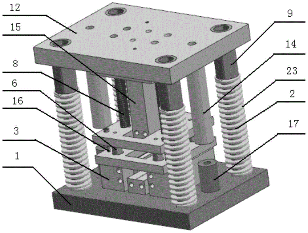
[0030] In the device designed by the present invention, at least the guide post 2 and the discharge rod 8 can move relative to the upper mold base 12 in the vertical direction, but the components including the guide post 2 and the discharge rod 8 cannot be extended. Out of the upper mold base 12.

[0031] In the experimental device structure of the present invention, as Figure 5-6 As shown, there are through holes on the punch 15, the bottom plate 19 of the die and the die plate 3, and its function is, for example, to insert a thermal resistor to heat the device, so that it can realize the functions of heating the blank and warm stamping.

[0032] Depend on Figure 3-6 It can be seen from the middle structure that the device provided by the present invention can keep the blank holder force constant during the ...


PUM


Abstract

The invention provides a punching device for an automotive aluminum plate. The punching device comprises an upper die assembly and a lower die assembly. The upper die assembly comprises a platy upper die holder, an upper clamping plate, a columnar male die, upper die limiting columns, guide sleeves and a constant-force edge pressing assembly. The upper die holder is arranged at the topmost end of the device and is horizontally arranged. The upper clamping plate is arranged on the lower surface of the upper die holder. One end of each columnar male die is fixedly arranged on the upper die holder, and the free end of each columnar male die faces downwards. One end of each upper die limiting column is fixedly arranged on the upper die holder, and the free end of each upper die limiting column faces downwards. One end of each guide sleeve is fixedly arranged on the upper die holder, and the free end of each guide sleeve faces downwards. The constant-force edge pressing assembly is arranged below the upper clamping plate. According to the forward punching device, the male dies are arranged on the upper portion, female dies are arranged on the lower portion, the design that constant-force edge pressing is achieved through two stages of springs, and the punching experiment can be conducted on a single-acting hydraulic machine.

Description

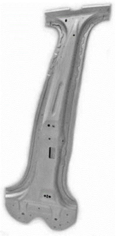
technical field [0001] The invention relates to the technical field of aluminum material forming, in particular to a stamping device and a stamping method for an aluminum plate for a vehicle. Background technique [0002] The forming and manufacturing of aluminum plate stamping parts for vehicles involves processes such as bending deformation, deep drawing deformation and bulging forming, such as figure 1 The B-pillar of a car. During the stamping process, applying blank holder force can prevent the sidewall or flange of the workpiece from wrinkling and reduce springback. The ideal blank-holding force should be the largest at the beginning of deep drawing, and gradually decrease as the deep-drawing process progresses, or at least keep the blank-holding force constant. However, in the single-stage spring blank-holding method adopted in the design of the existing common stamping dies, the blank-holding force increases with the increase of the stroke (drawing depth), which is...

Claims


Application Information

Patent Timeline
Patent Type & Authority Patents(China)
IPC IPC(8): B21D22/06B21D37/10B21D37/12B21D53/88
CPCB21D22/06B21D37/10B21D37/12B21D53/88
Inventor 湛利华赵俊徐凌志郭亮
Owner CENT SOUTH UNIV
Learn More