
Traction device of wire drawing machine

The technology of a traction device and a wire drawing machine is applied in the field of metal wire drawing equipment, which can solve the problems of fixed winding size, easy skew of the winding shaft and influence on the winding quality, etc. simple effect

Active Publication Date: 2015-08-26
NANTONG HUWANG PLASTIC SCI & TECH DEV CO LTD
View PDF6 Cites 2 Cited by
  • Summary
  • Abstract
  • Description
  • Claims
  • Application Information

AI Technical Summary

Problems solved by technology

The existing winding head adopts an integrated winding shaft, and the winding size is fixed and cannot be changed
In addition, the existing winding head adopts unilateral drive, and the winding shaft is easy to be skewed, which affects the winding quality

Method used


Image

  • Traction device of wire drawing machine
  • Traction device of wire drawing machine
  • Traction device of wire drawing machine

Examples


Embodiment Construction

[0015] The preferred embodiments of the present invention will be described in detail below in conjunction with the accompanying drawings, so that the advantages and features of the present invention can be more easily understood by those skilled in the art, so as to define the protection scope of the present invention more clearly.

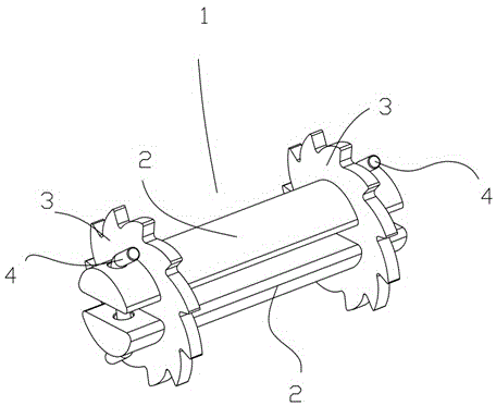
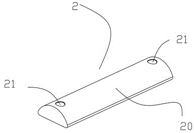
[0016] like Figure 1 to Figure 4 As shown, the traction device 1 of the wire drawing machine includes a pair of connecting horizontal bars 2 arranged in parallel, and a detachable driving ratchet 3 is respectively provided at both ends of the connecting horizontal bars 2, and the connecting horizontal bar 2 includes a long horizontal bar Bar main body 20, the two ends of this bar main body 20 are provided with a bar circular hole 21 respectively, the section of this bar main body 20 is fan-shaped, and this drive ratchet 3 comprises a disc-shaped wheel disc 31, and the wheel disc 31 A ratchet array consisting of ratchets 32 is provided on the edg...


PUM


Abstract

The invention discloses a traction device of a wire drawing machine. The traction device of the wire drawing machine comprises a pair of connecting cross bars arranged in parallel, wherein detachable driving ratchet wheels are respectively arranged at the two ends of the connecting cross bars. The traction device of the wire drawing machine has the following advantages: when the wire drawing is performed, users can select the connecting cross bars with proper lengths according to the winding size, and install the driving ratchet wheels at the two sides of the connecting cross bars. As double driving ratchet wheels are adopted, the rotating speed of the connecting cross bars is uniform, the winding torque is high, and the winding efficiency of the wire drawing machine is greatly improved; and the traction device of the wire drawing machine is simple in structure, excellent in flexibility and strong in practicability.

Description

technical field [0001] The invention relates to a metal wire drawing equipment, more precisely, a drawing device of a wire drawing machine. Background technique [0002] Wire drawing machine is a common metal processing equipment. As the name suggests, it is to draw thick metal wire into thin wire. There is usually a winding head at the tail of the wire drawing machine, which is used for winding while drawing. The existing winding machine head adopts an integrated winding shaft tube, and the winding size is fixed and cannot be changed. In addition, the existing winding head adopts unilateral drive, and the winding shaft is easily skewed, which affects the winding quality. Contents of the invention [0003] The present invention mainly solves the technical problems existing in the prior art, thereby providing a drawing device for a wire drawing machine. [0004] Above-mentioned technical problem of the present invention is mainly solved by following technical scheme: ...

Claims


Application Information

Patent Timeline
Patent Type & Authority Applications(China)
IPC IPC(8): B21C1/14
CPCB21C1/14
Inventor 于浩
Owner NANTONG HUWANG PLASTIC SCI & TECH DEV CO LTD
Learn More