
burner

A technology of burners and diffusion elements, applied in the direction of burners, gas fuel burners, combustion methods, etc., which can solve the problems of performance degradation, dirty holes, clogging, etc.

Inactive Publication Date: 2017-05-10
ANCORA
View PDF7 Cites 0 Cited by
  • Summary
  • Abstract
  • Description
  • Claims
  • Application Information

AI Technical Summary

Problems solved by technology

All this inevitably translates into increased investment costs, and more complex inventory management and maintenance
[0013] Another drawback of the known type of burner is that the holes formed near the central seat of the diffuser tend to become dirty and clogged over time, requiring periodic maintenance and / or replacement work, and in one working and Experience a rapid drop in performance between jobs
[0014] Another drawback of known types of burners consists in that they do not allow any flow regulation of the combustion fluid distributed towards the combustion zone

Method used


Image

  • burner
  • burner
  • burner

Examples


Embodiment Construction

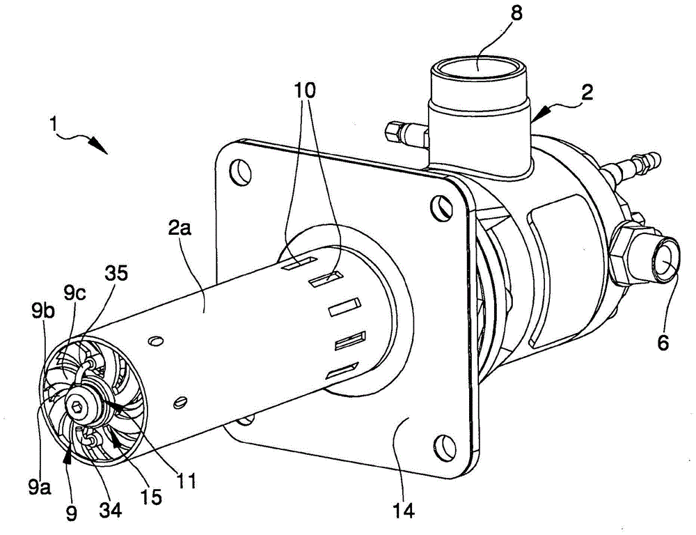
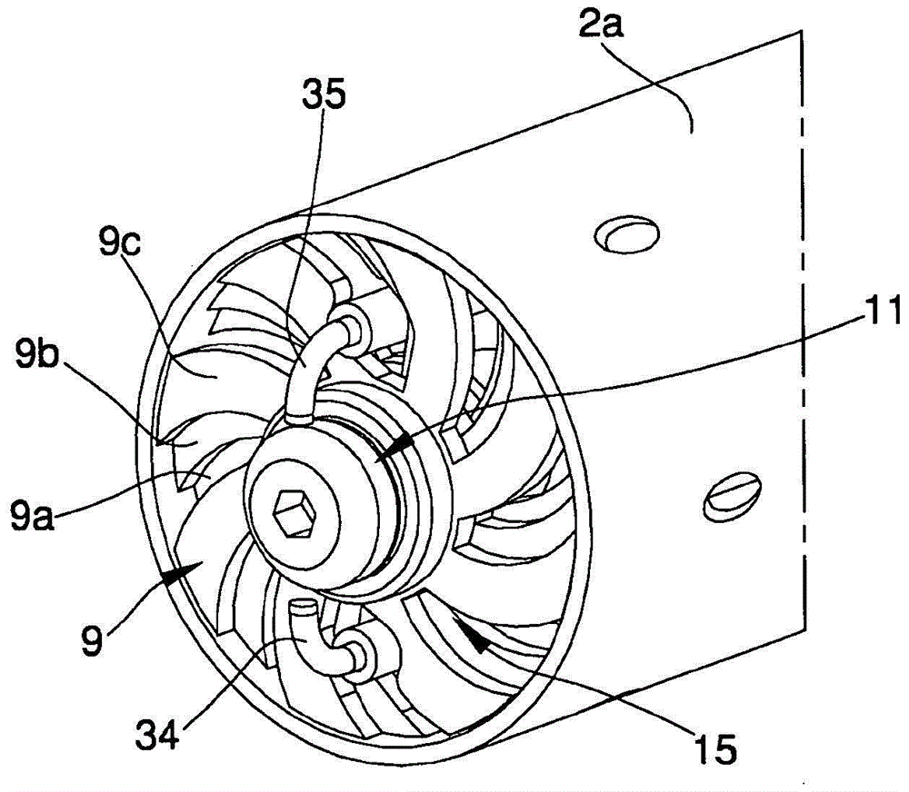
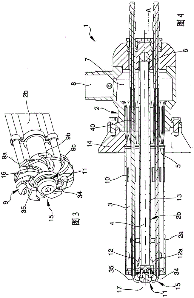
[0037] With particular reference to these figures, a burner according to the invention, indicated throughout by 1, can be used both in the industrial and civil fields.

[0038] The burner 1 comprises a support body 2 defining at least a first duct 3 for supplying a combustible fluid and at least a second duct 4 for supplying a combustion fluid.

[0039] More specifically, the supporting body 2 comprises a first tubular element 2 a defining a first duct 3 and a second tubular element 2 b defining a second duct 4 . The word "tubular" as used herein refers to any internally hollow element, regardless of its cross-sectional shape, which may be of any shape.

[0040] In the illustrated embodiment, the second tubular element 2b is arranged inside the first tubular element 2a. Thus, more specifically, the first duct 3 is delimited laterally by the first and second tubular elements 2a and 2b, while the second duct 4 is delimited laterally only by the second tubular element 2b. In th...


PUM


Abstract

The burner comprises a supporting body having a first and a second tubular elements (2a, 2b), where the volume positioned between the first and the second tubular elements (2a, 2b) defines at least a first duct (3) for the flow of a combustive fluid and where the second tubular element (2b) defines at least a second duct (4) for the flow of a combustion fluid; the second tubular element (2b) comprising a union element (12) defining an extremity section of said second duct (4); a combustion head (15) associated with the supporting body (2) and comprising diffusing means (9), communicating with the first duct (3) and having a plurality of openings (16) for the flow of the combustive fluid towards a combustion area (17), where the diffusing means (9) comprise at least two diffusing elements (9a, 9b, 9c) having relative openings for the flow of the combustive fluid and mobile reciprocally the one to the other to change the relative position of the openings, and dispensing means (11) of the combustion fluid, communicating with the second duct (4) and having a plurality of gaps (18) for the flow of the combustion fluid itself towards the combustion area (17); the diffusing elements (9a, 9b, 9c) are fitted around the union element (12), each of them has a plurality of openings defined by respective through cuts extending along a portion of the relative diffusing element (9a, 9b, 9c), where the openings have a substantially curvilinear extension and have a growing section proceeding outwards, and the union element (12) has at least a section (12a) which diverges proceeding towards the diffusing elements (9a, 9b, 9c), where the diverging section (12a) protrudes inside the first duct (3) and is suitable for directing the combustive fluid flow towards the outer portions of the openings.

Description

technical field [0001] The present invention relates to a burner that can be used in the industrial field and the civil field. Background technique [0002] Burners are used, for example, in the ceramics industry, in plants for the heat treatment of ceramic products, such as kilns and dryers. [0003] Burners of known type are generally made of a support body defining air supply ducts and combustion gas supply ducts, and a combustion head, said ducts being placed in communication with the combustion zone through the combustion head. [0004] The combustion head in turn includes an air diffuser having a plurality of openings which communicate with the air supply ducts to direct air to the combustion zone, and a gas distribution member having a plurality of flow gaps which communicate with the A gas supply conduit communicates to deliver gas toward the combustion zone. [0005] Thus, in the combustion zone, air is mixed with combustion gases. [0006] The diffuser of the co...

Claims


Application Information

Patent Timeline
Patent Type & Authority Patents(China)
IPC IPC(8): F23C7/00F23D14/24F23D14/48
CPCF23C7/006F23D14/24F23D14/48F23D2203/1017
Inventor 本费纳蒂·阿尔贝托
Owner ANCORA
Learn More