Method of optimizing stress equilibrium in switching power supply and switching power supply to which method is applied

A technology of switching power supply and optimization method, which is applied in the direction of electrical components, output power conversion device, AC power input conversion to DC power output, etc., to achieve the effect of reducing cost, shortening development cycle, and reducing the probability of occurrence

Active Publication Date: 2015-08-19
MORNSUN GUANGZHOU SCI & TECH
View PDF5 Cites 8 Cited by
  • Summary
  • Abstract
  • Description
  • Claims
  • Application Information

AI Technical Summary

Problems solved by technology

The existing switching power supply topology design method is not suitable for the new topology in the above patents, and reasonable design of inductors, capacitors and transformers can broaden the input voltage range of switching power supply and reduce output ripple

Method used


Image

  • Method of optimizing stress equilibrium in switching power supply and switching power supply to which method is applied
  • Method of optimizing stress equilibrium in switching power supply and switching power supply to which method is applied
  • Method of optimizing stress equilibrium in switching power supply and switching power supply to which method is applied

Examples


no. 1 example

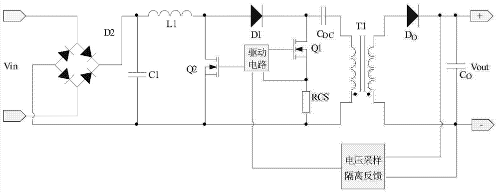
[0032] image 3 Shown is the circuit schematic diagram of the switching power supply according to the first embodiment of the present invention. A switching power supply includes a rectifier bridge 101, a first capacitor C1, a Boost circuit, a first switching tube Q1, and a second capacitor C DC , Flyback circuit, the Boost booster circuit includes an inductor L1, a second switch tube Q2, and a first diode D1; the flyback circuit includes a first transformer T1, an output diode Do (output rectifier diode), a third capacitor Co (output capacitance). The rectifier bridge 101 rectifies the alternating current into a pulsating direct current, and the two ends of the first capacitor C1 are respectively connected to the positive output terminal and the negative output terminal of the rectifier bridge 101; the boost circuit boosts the output voltage of the rectifier bridge 101 High, the positive output end of the rectifier bridge 101 is connected to one end of the inductance L1 in t...

Embodiment 2

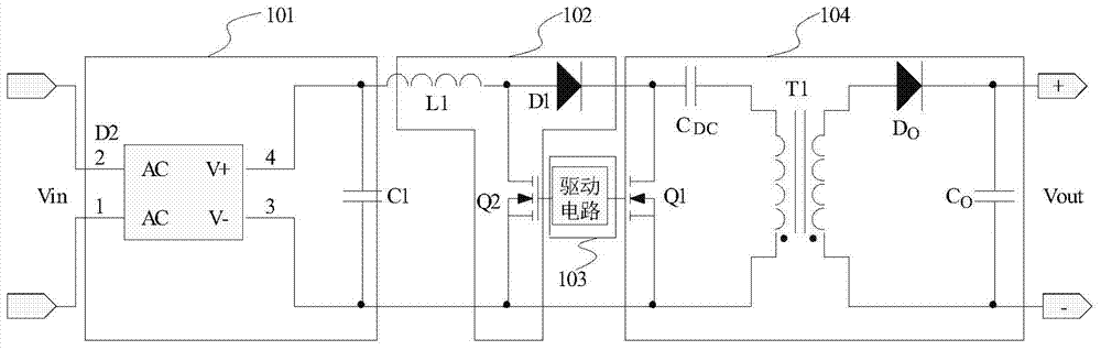
[0070] The secondary side of the second embodiment is the same as that of the first embodiment, and the structure of the rectifier circuit and the flyback circuit of the primary side is also the same, so I won’t go into details here, and mainly explain the differences between the two—voltage doubler circuit, voltage doubler circuit One end of the inductance L1 is connected to the positive output end of the rectifier bridge, the other end of the inductance L1 in the voltage doubler circuit is connected to the cathode of the second diode D2, and connected to the anode of the first diode D1, and the anode of the second diode D2 The anode is connected to the negative output terminal of the rectifier bridge, the cathode of the first diode D1 is connected to the drain of the first switch tube and one end of the second capacitor CDC, and the other end of the second capacitor CDC is connected to the opposite end of the primary winding of the transformer .

[0071] Assuming that the co...


PUM


Abstract

The invention discloses a method of optimizing stress equilibrium in a switching power supply, which comprises steps: a first diode is used for building an energy matching relationship among a first capacitor, an inductor and a transformer, that is, when a switching tube is conducted, an exciting circuit of the inductor and an exciting circuit of the transformer are separated via the first diode, when the switching tube is cutoff, the inductor and the transformer are connected via the first diode, within a half power frequency cycle, the first capacitor is divided into a charging period and a non-charging period, and when the first capacitor is in the non-charging period, the first diode is in a non-conduction period; the average power when the first capacitor is in the charging period and the average power when the first capacitor is in the discharging period are regarded as the same; and according to the energy matching relationship among the inductor, the first capacitor and the transformer, the principle of conservation of energy is used, and the inductor parameter selection range is calculated by the capacitance value of the first capacitor, the transformer turn ratio and the source-side winding inductance. Compared with the prior art, voltage stress of each element can be balanced, and electromagnetic interference caused by a large voltage change rate can be reduced.

Description

technical field [0001] The present invention relates to a design method of a power supply circuit, in particular to an optimization method of stress balance in a switching power supply whose primary side is a three-order system (there are two magnetic elements and a capacitive element in the main power) and a switch applicable to the method power supply. Background technique [0002] Power supply is various forms of circuit devices required to convert electrical energy into electrical equipment, and it is the source of power for all devices that work on electrical energy. DC switching power supply is a power conversion device composed of a switching circuit controlled by a duty ratio, and is widely used in various fields such as life, production, scientific research, and military affairs. [0003] The capacitors used in the front stage of switching power supplies are generally selected from aluminum electrolytic capacitors. Aluminum electrolytic capacitors are widely used d...

Claims


Application Information

Patent Timeline
IPC IPC(8): H02M1/34H02M7/217
Inventor 郭启利黄天华
Owner MORNSUN GUANGZHOU SCI & TECH
Why Eureka
Try Eureka