Fixtures for large test boards
A technology for testing circuit boards and clamping devices, applied in the direction of the measuring device casing, etc., can solve problems such as inconvenient use, and achieve the effects of easy installation and use, easy portability, and low cost of use
- Summary
- Abstract
- Description
- Claims
- Application Information
AI Technical Summary
Problems solved by technology
Method used
Image

Examples
Embodiment Construction
[0018] The present invention will be further explained below in conjunction with the drawings and embodiments. In the following detailed description, only certain exemplary embodiments of the present invention are described by way of illustration. Needless to say, those of ordinary skill in the art can realize that the described embodiments can be modified in various ways without departing from the spirit and scope of the present invention. Therefore, the drawings and description are illustrative in nature, and are not used to limit the protection scope of the claims.
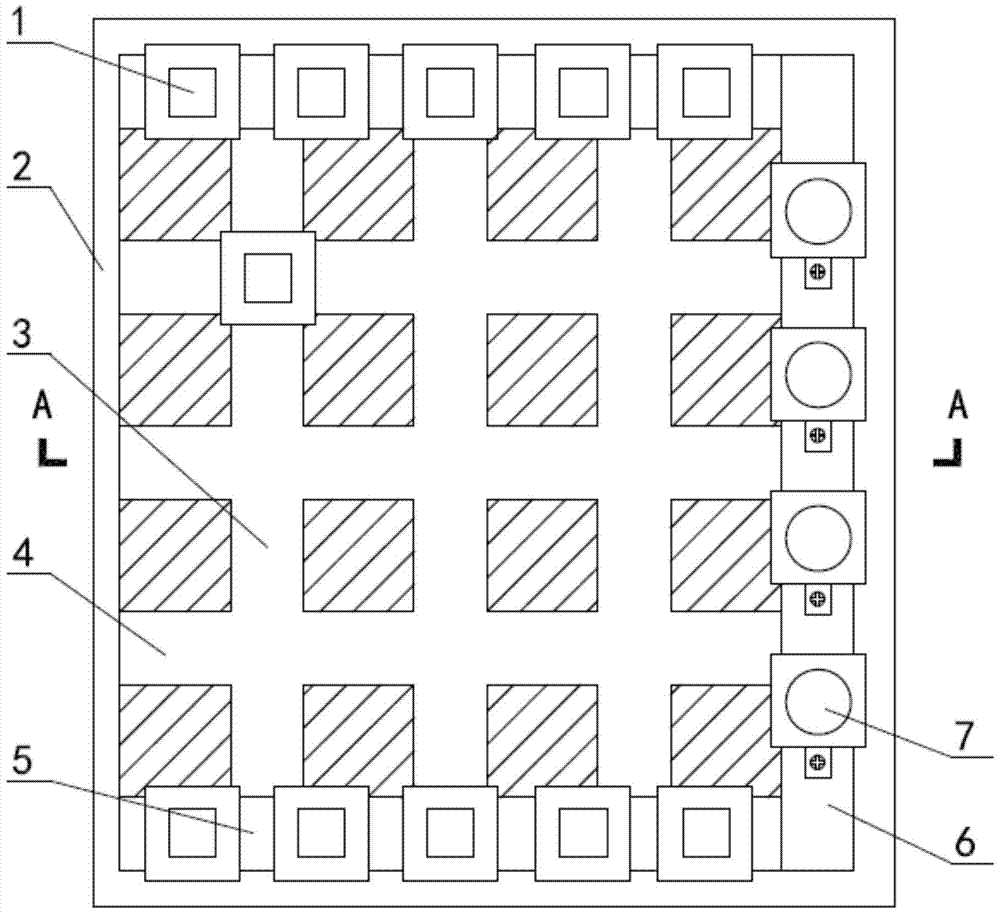
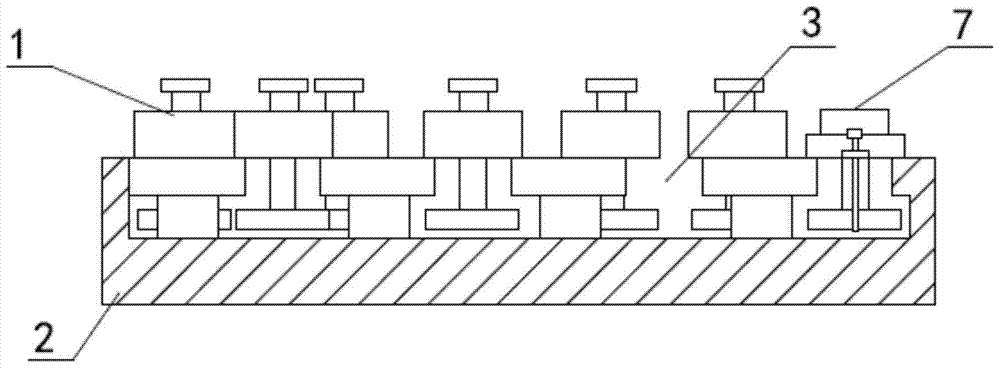
[0019] Such as figure 1 , figure 2 , image 3 , Figure 4 As shown, the clamping device for a large test circuit board includes a bottom plate 2. The bottom plate 2 is provided with a number of transverse T-shaped guide chutes 4, corresponding to the transverse T-shaped guide chute 4, a number of longitudinally opened on the bottom plate 2 The longitudinal T-shaped guide chute 3 is matched and communicated with...
PUM
 Abstract
Description
Claims
Application Information
 - Generate Ideas
- Intellectual Property
- Life Sciences
- Materials
- Tech Scout
- Unparalleled Data Quality
- Higher Quality Content
- 60% Fewer Hallucinations
Browse by: Latest US Patents, China's latest patents, Technical Efficacy Thesaurus, Application Domain, Technology Topic, Popular Technical Reports.
© 2025 PatSnap. All rights reserved.Legal|Privacy policy|Modern Slavery Act Transparency Statement|Sitemap|About US| Contact US: help@patsnap.com