Trinity quantitative water injection device
A three-in-one, water distribution device technology, applied in the fields of production fluids, wellbore/well components, earthwork drilling, etc., can solve the problems of complex sealing inspection, poor pressure bearing capacity of packers, and cumbersome casting and distribution process, etc. Check and replace the convenient effect of the faucet
- Summary
- Abstract
- Description
- Claims
- Application Information
AI Technical Summary
Problems solved by technology
Method used
Image
Examples
Embodiment 1
[0035] Such as figure 1 As shown, the three-in-one quantitative water injection device includes a working cylinder 1 and a water distribution core 2 arranged in the working cylinder 1. The water distribution core 2 is composed of three identical water distribution devices 3. The water outlet A4 set on the water distribution device 3 is connected to the working The water outlet B5 opened on the cylinder 1 corresponds; the working cylinder 1 is composed of an upper cylinder body 6, a middle cylinder body 7, a lower cylinder body 8 and two isolation devices 9; one of the isolation devices 9 is set on the upper cylinder Between the middle cylinder body 6 and the middle cylinder body 7, another sealing device 9 is arranged between the middle cylinder body 7 and the lower cylinder body 8.
[0036] The traditional water injection process adopts the working principle of graded water distribution and single use, that is, one water distribution core 1 is arranged on one layer. The fishi...
Embodiment 2
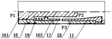
[0039] This embodiment is on the basis of embodiment 1, as figure 2 As shown, the water distribution device 3 includes an outer cylinder 10, a water nozzle 11 arranged in the outer cylinder 10; Ring 13, the protruding ring 13 is provided with a second water inlet 14 that runs through the front and rear end faces of the protruding ring 13, and the protruding ring 13 is provided with a water outlet A4 radially penetrating the outer cylinder 10, and the water outlet A4 is not connected to the second water inlet 14 A third water inlet 15 is provided at the bottom of the outer cylinder, and the third water inlet 15 communicates with the second water inlet 14; the water nozzle 11 includes a plunger 16, and the plunger 16 is composed of a large diameter section 161 and a small diameter section 162, The large-diameter section 161 is slidably arranged on the convex ring 13, and the outer surface of the large-diameter section 161 is in contact with the inner surface of the convex ring 13...
Embodiment 3
[0051] On the basis of Embodiment 2, this embodiment also includes a connecting column A20 and a connecting column B21. The two ends of the connecting column A20 are respectively connected to the bottom of the upper water distribution device 3 and the top of the Chinese water distribution device 3. The bottom of the Chinese water distribution device 3 and the top of the lower water distribution device 3 are connected; the outer surface of the connecting column A20 and the inner surface of the working cylinder 1 form a popular channel A22, and the outer surface of the connecting column B21 and the inner surface of the working cylinder 1 form a popular channel B23. The upper cylinder body 6 is provided with an upper channel 24 , one end of which runs through the front end of the upper cylinder body 6 , and the other end communicates with the popular channel A.
[0052] This embodiment can realize the water injection to the middle water injection layer, specifically as follows: wa...
PUM
 Abstract
Description
Claims
Application Information
 - R&D
- Intellectual Property
- Life Sciences
- Materials
- Tech Scout
- Unparalleled Data Quality
- Higher Quality Content
- 60% Fewer Hallucinations
Browse by: Latest US Patents, China's latest patents, Technical Efficacy Thesaurus, Application Domain, Technology Topic, Popular Technical Reports.
© 2025 PatSnap. All rights reserved.Legal|Privacy policy|Modern Slavery Act Transparency Statement|Sitemap|About US| Contact US: help@patsnap.com


