
Rotating impact acceleration device and method of power drilling tool

A technology of power drilling tools and impact hammers, which can be applied to the driving device for drilling in boreholes, drilling equipment, earthwork drilling and production, etc. It can solve the problems of inability to match power drilling tools, unaffordable speed-up tools, and failure to cause downhole accidents, etc. , it is easy to adjust the impact amplitude, it is beneficial to work for a long time, and it is beneficial to transportation and use

Active Publication Date: 2015-08-19
CHINA UNIV OF PETROLEUM (EAST CHINA)
View PDF7 Cites 26 Cited by
  • Summary
  • Abstract
  • Description
  • Claims
  • Application Information

AI Technical Summary

Problems solved by technology

The following problems exist in the speed-up in directional wells: (1) The drill bit is directly connected to the power drilling tool, and long-sized speed-up tools cannot be added in between; (2) The work of the speed-up tool cannot affect the use of the measurement-while-drilling tool; (3) The service life of the tool should not be too short , which is at least similar to the life of the power drilling tool; (4) When the tool has an accident, it cannot cause a downhole accident; (5) The use of the speed-up tool cannot provide a burden for the rotation of the power drilling tool
However, some of these tools have complex structures and short working life, which are difficult to meet the needs of the site; some are too large to match with power drilling tools, and some cannot be used together with measurement-while-drilling instruments. The above factors lead to the above-mentioned types of rotational impact Drilling tools have not been used in the field of speed increase in directional wells

Method used


Image

  • Rotating impact acceleration device and method of power drilling tool
  • Rotating impact acceleration device and method of power drilling tool
  • Rotating impact acceleration device and method of power drilling tool

Examples


Embodiment Construction

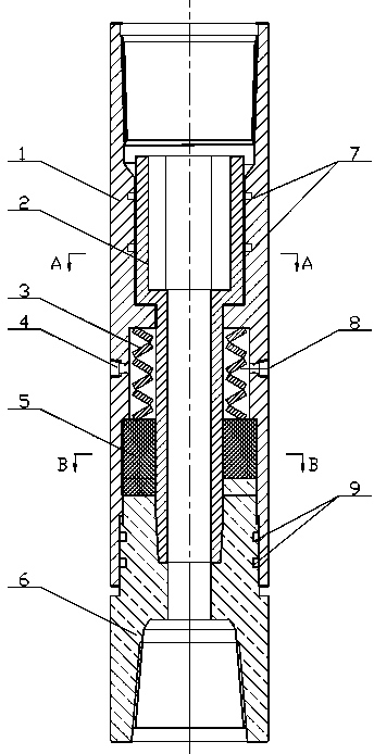
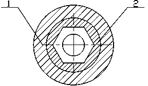
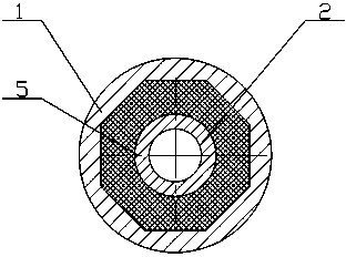
[0032] Such as figure 1 , figure 2 , image 3 As shown, the rotary impact acceleration device for power drilling tools mentioned in the present invention includes a stator outer cylinder 1, a rotor transmission shaft 2, an impact storage spring 3, an active toothed impact hammer 5, and a passive impact transmission joint 6.

[0033] Such as Figure 4 As shown, the outside of the stator outer cylinder 1 is a cylindrical surface of equal diameter, and the inside is sequentially from top to bottom a power drilling tool casing connecting buckle 101, a transmission shaft support surface 102, a transmission shaft anti-off end surface 103, and a transmission shaft support surface. 104, the spring supporting surface 105, the spring outer cylinder 106, the twisting surface 107, the rotating sealing end surface 108; the power drilling tool casing connecting buckle 101 is used to connect the power drilling tool casing; the outer diameter of the transmission shaft supporting surfac...


PUM


Abstract

The invention relates to a rotating impact acceleration device and a method of a power drilling tool. The device is characterized in that a rotor transmission shaft, a driving tooth-shaped impact hammer and a driven impact transmission joint are mounted at the inner side of a stator outer cylinder; the lower end of the rotor transmission shaft is in threaded connection with the driven impact transmission joint; the middle part of the rotor transmission shaft and the middle part of the stator outer cylinder are formed to a cylindrical cavity; an impact force accumulating spring is mounted in the cavity; the lower end of the impact force accumulating spring fits the driving tooth-shaped impact hammer; a tooth-shaped curved surface is arranged at the lower end of the driving tooth-shaped impact hammer, and is engaged with a tooth-shaped curved surface at the upper end of the driven impact transmission joint; the driven impact transmission joint is driven by the rotor transmission shaft to generate a rotating motion corresponding to the driving tooth-shaped impact hammer; and the driving tooth-shaped hammer and the impact force accumulating spring generate axial reciprocating impact on the driven impact transmission joint to realize the rotation and the impact. The device is simple in structure and shorter in length, and dose not influence the operations of the power drilling tool and a measuring tool while drilling.

Description

technical field [0001] The invention relates to the field of petroleum engineering, in particular to a device and method for speed-increasing by rotary impact of a power drilling tool. Background technique [0002] Directional wells are currently the most important well type for oil and gas field development. However, as the depth of oil and gas reservoirs continues to increase, the problem of slow drilling speed becomes more prominent. How to increase the speed in directional wells is one of the important research directions of petroleum engineering technology. The following problems exist in the speed-up in directional wells: (1) The drill bit is directly connected to the power drilling tool, and long-sized speed-up tools cannot be added in between; (2) The work of the speed-up tool cannot affect the use of the measurement-while-drilling tool; (3) The service life of the tool should not be too short , at least similar to the life of the power drilling tool; (4) When th...

Claims


Application Information

Patent Timeline
IPC IPC(8): E21B4/16
CPCE21B4/16
Inventor 刘永旺管志川
Owner CHINA UNIV OF PETROLEUM (EAST CHINA)
Learn More