Skin tester

A skin tester and tester technology, applied in the field of testers, can solve the problems of cumbersome operation and use, cannot be used alone, and difficult to operate, and achieve the effects of convenient operation, easy to use alone, and avoiding damage to the instrument

Active Publication Date: 2015-08-19
ECOVACS ROBOTICS (SUZHOU ) CO LTD
View PDF9 Cites 3 Cited by
  • Summary
  • Abstract
  • Description
  • Claims
  • Application Information

AI Technical Summary

Problems solved by technology

[0003] There are two main types of skin testers currently on the market. One is a special tester for TV, but the user of the tester needs to master professional knowledge, the operation is difficult, and requires a lot of energy and time; the other is a wireless tester. Portable tester, which uses wireless transmission and reception technology to connect with TV or computer, and is equipped with a series of camera lenses at the same time, so as to take pictures of the skin surface, and use the lens to enlarge the skin pictures taken for test and analysis, but it has the disadvantage of single function and cannot be used alone At the same time, there are many buttons on the instrument, such as switch machine, function selection, power button, etc., and the user's operation is cumbersome. Therefore, it is urgent to study a skin tester with exquisite design, simple operation, reliable performance, and various functions.

Method used


Image

  • Skin tester
  • Skin tester
  • Skin tester

Examples


Embodiment 1

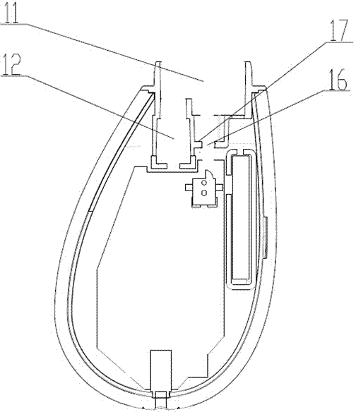
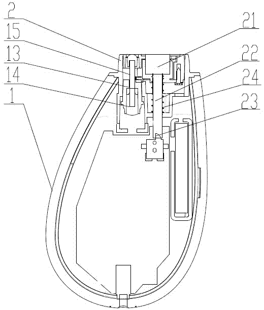
[0035] The invention discloses a skin tester, as attached figure 1 , attached figure 2 And attached Figure 4 As shown, it includes a body 1, a protective cover 4 that can be separated from the body 1, a test head 2 arranged on the body 1 and a power supply device arranged in the body 1, and the test head 2 includes a sensor assembly 21. The sensor assembly 21 is any one or more of capacitive sensors, photochemical sensors, and elastic sensors. The test head 2 also includes a trigger rod 22 arranged below the sensor assembly 21. The test The head 2 can be axially slidably locked in the card slot 11 opened at the upper end of the body 1, and the trigger lever 22 is connected or disconnected with the signal switch 23 at the bottom of which the gap is arranged; in order to control the test head 2 slide in the card slot, the test head 2 is also provided with a limit mechanism and an automatic reset mechanism to limit the slide of the test head 2.

[0036] The limiting mechanis...

Embodiment 2

[0043] The overall structure and work process of this embodiment and embodiment 1 are similar, and its difference is: as attached Figure 5 , attached Figure 6 As shown, the test head 2 includes a body 25, the body 25 includes a top opening and a side wall opening, on which a rotating shaft 7 fixed on the sensor assembly 21 is erected; the power switch device includes a set A power trigger device 8 at one end of the rotating shaft 7 and capable of following the rotation of the rotating shaft 7 and a power switch 9 arranged on the body 25 of the test head 2; as attached Figure 7 As shown, the power trigger device 8 is an eccentric bump, which includes a semi-arc-shaped boss 81 and a plane 82, and the power switch 9 includes a contact 91, and the upper end surface of the contact 91 is arc-shaped The elastic contact, which can be made of elastic material, can also be arranged on the power switch 9 through elastic parts or quick-change parts; the sensor assembly 21 and the rota...

Embodiment 3

[0048] The overall structure and work process of this embodiment and embodiment 1 are similar, and its difference is: as attached Figure 10 As shown, the triggering device includes an axial rib 41 arranged on the inner wall of the protective cover 4, and the triggered device includes a concave groove on the test head 2 that matches the rib 41. Groove 26, there is a switch guide rod 27 that can slide axially in the groove 26, a return spring is arranged on the switch guide rod 27, and a power switch is arranged in the gap at its end, the power switch and the Power unit connection. When the protective cover 4 is assembled on the test head 2, the rib 41 on the protective cover 4 will be inserted into the groove 26 on the test head 2, and press the switch guide rod 27 to move downward, so that The switch guide rod 27 triggers the power switch to cut off the power supply of the machine; after the protective cover 4 is pulled out, the switch guide rod 27 has no downward force,...


PUM


Abstract

The invention discloses a skin tester. The skin tester comprises a machine body, a power supply device and a testing head arranged on the machine body, wherein the testing head comprises a sensor component. The tester further comprises a power supply switch device capable of switching on and switching off the power supply device in one step and a signal transceiver arranged in the machine body and used for being communicated with the user side. The skin tester is elaborate in design, reasonable in structure and convenient to operate. By arranging a sensing device automatic starting structure and multiple power supply starting structures and omitting various starting buttons arranged on a skin tester in the prior art, production cost is reduced. The signal transceiver matched with the user side is arranged to be matched with mobile terminals such as mobile phones and tablet computers, the 3G technology is fully utilized, accessories such as function keys and a display screen on the skin tester are omitted, a user does not need to set the skin tester, operation is extremely convenient, and the skin tester can be used conveniently by the user alone.

Description

technical field [0001] The invention relates to a tester, in particular to a skin tester without a power button on the surface. Background technique [0002] With the development of the economy and the continuous improvement of people's living standards, people's awareness of health care is constantly strengthening. Therefore, with the rapid advancement of science and technology, various types of skin care equipment have entered the market one after another. [0003] There are two main types of skin testers currently on the market. One is a special tester for TV, but the user of the tester needs to master professional knowledge, the operation is difficult, and requires a lot of energy and time; the other is a wireless tester. Portable tester, which uses wireless transmission and reception technology to connect with TV or computer, and is equipped with a series of camera lenses at the same time, so as to take pictures of the skin surface, and use the lens to enlarge the skin...

Claims


Application Information

Patent Timeline
IPC IPC(8): A61B5/00
CPCA61B5/0002A61B5/443
Inventor 彭中美钱程
Owner ECOVACS ROBOTICS (SUZHOU ) CO LTD
Why Eureka
Try Eureka