
Actuator

A technology of actuators and actuators, which is applied to electric components, engine components, engine control, etc., can solve the problems of heavy casing weight, and achieve the effect of small weight and close contact

Inactive Publication Date: 2015-08-12
CONTINENTAL AUTOMOTIVE GMBH
View PDF6 Cites 1 Cited by
  • Summary
  • Abstract
  • Description
  • Claims
  • Application Information

AI Technical Summary

Problems solved by technology

This housing is therefore heavier

Method used


Image

  • Actuator
  • Actuator
  • Actuator

Examples


Embodiment Construction

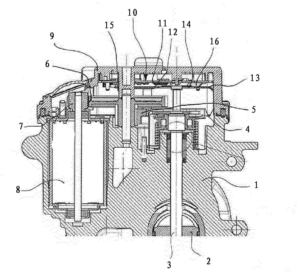
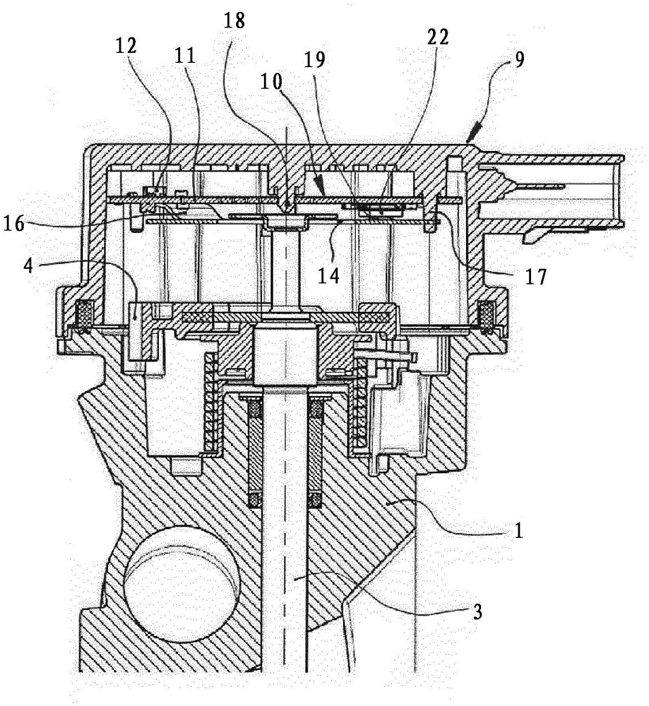
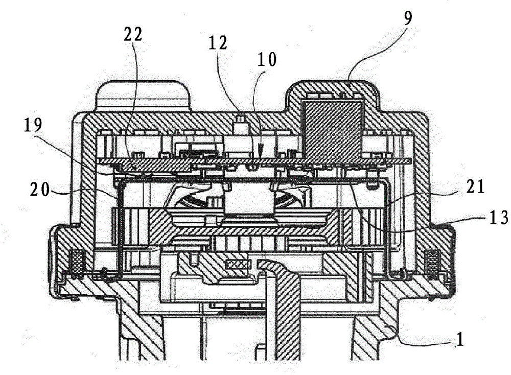
[0023] figure 1 Shown is part of a housing 1 made of aluminum of an actuator in a motor vehicle with an actuator 2 driven by a pinion 7 of an electric motor 8 via a shaft 3 , gears 4 - 6 . The motor 8 is arranged in a chamber of the housing 1 . A plastic cover 9 is connected to the housing 1, wherein the plastic cover 9 covers the area of ​​the motor 8 and the gears 4-6. For controlling the motor 8 as a function of the position of the actuator 2 , an electronic device 10 is provided. The electronic device 10 is composed of a circuit board 11 and electrical structural elements 12 disposed thereon. A metal body functioning as a heat sink 13 is provided between the gears 4 - 6 and the electronic device 10 . In the area of ​​the shafts of the gearwheels 4 - 6 the heat sink 13 has recesses 14 , 15 . The plate 16 of the heat sink 13 is used as a thermal connection surface and is in contact with the electronic device 10 under a preload.

[0024] figure 2 The housing 1 is shown...


PUM


Abstract

The invention relates to an actuator comprising a metal housing (1) that consists of multiple housing parts (1, 9), an electric motor (8), an actuating member (2), a transmission mechanism (4-7) that adapts the movement of the electric motor (8) to the actuating member (2) and an electronic system (10) for controlling the electric motor (8). At least one housing part (9) consists of plastic, a heat sink (13) being situated in the region of the housing part (9) that consists of plastic. The heat sink (3) has thermal connecting surfaces (16, 19) for the electronic system (10) and is connected to a metal housing part (1).

Description

technical field [0001] The invention relates to an actuator having a metal housing consisting of a plurality of housing parts, a motor, an actuator, a transmission mechanism for adapting the movement of the motor to the actuator and a device for controlling the motor electronic device. Background technique [0002] Actuators of this type with motor-driven flap-shaped, pin-shaped actuating elements, or are used in motor vehicles as regulators or valves, are therefore known. The metal housings used are usually cast aluminum housings because they are relatively light and sufficiently rigid. In order to be able to install the structural element into the housing, the housing is composed of two or more housing parts. Since actuators are often exposed to high temperatures in motor vehicles, multipart aluminum housings are used due to their good thermal conductivity to cool structural parts arranged in the housing, in particular the electronics. It is also known in the use of act...

Claims


Application Information

Patent Timeline
Patent Type & Authority Applications(China)
IPC IPC(8): H02K5/08H02K11/00H02K7/116H02K9/22
CPCF02D2011/102H02K11/0073F02D11/10F02D9/1065F16K31/04F02D9/108H02K5/08H02K9/22H02K7/116H02K11/0068H02K9/227H02K11/30H02K11/33H02K11/40
Inventor J·冯 维利希C·赖曼V·克里米娜
Owner CONTINENTAL AUTOMOTIVE GMBH
Learn More