
Independent Control Method of Echo Gain in Gate for Ultrasonic Flaw Detector

An independent control, gain control technology, applied in the analysis of solids using sonic/ultrasonic/infrasonic waves, detection of response signals, etc.

Active Publication Date: 2017-07-25
NCS TESTING TECH
View PDF5 Cites 0 Cited by
  • Summary
  • Abstract
  • Description
  • Claims
  • Application Information

AI Technical Summary

Problems solved by technology

[0004] The purpose of the present invention is to provide an independent control method for the echo gain in the gate of the ultrasonic flaw detector, which is used to solve the problem that the echo signal gain in the gate needs to be adjusted separately during the flaw detection process

Method used


Image

  • Independent Control Method of Echo Gain in Gate for Ultrasonic Flaw Detector
  • Independent Control Method of Echo Gain in Gate for Ultrasonic Flaw Detector
  • Independent Control Method of Echo Gain in Gate for Ultrasonic Flaw Detector

Examples


Embodiment Construction

[0019] In view of the fact that most of the existing ultrasonic flaw detectors can only set a single gain value, which cannot meet the needs of simultaneously observing the bottom wave and the defect wave, the present invention provides a high-performance independent control method for the echo gain in the gate, and the following is combined with the attached The figures illustrate the invention in detail.

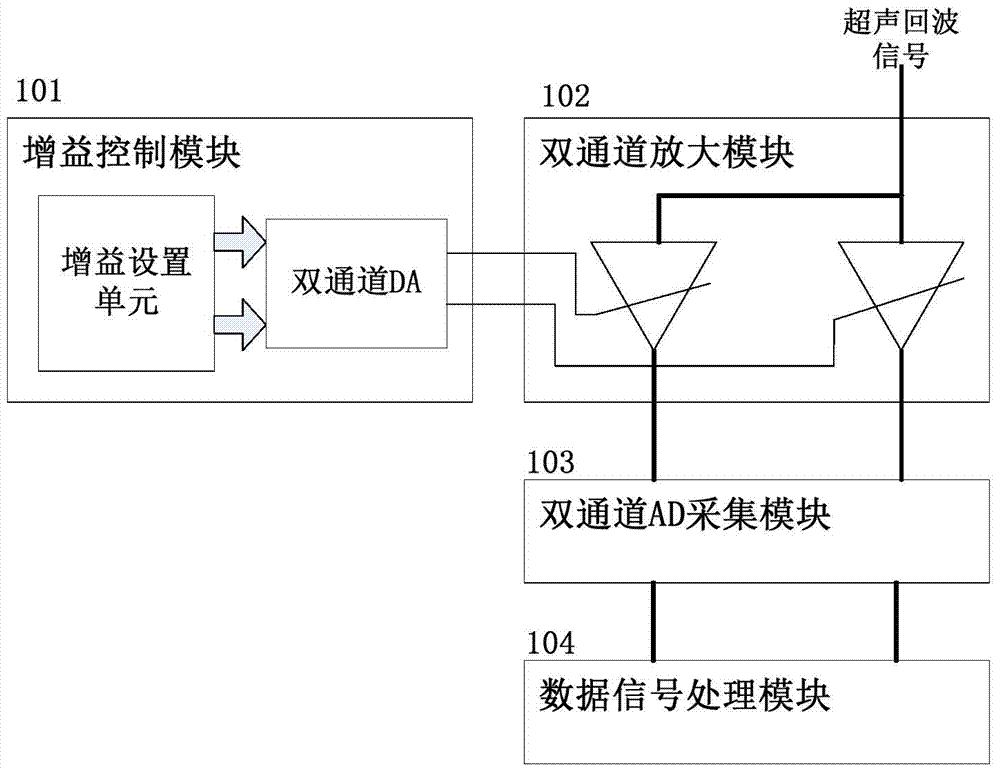
[0020] The structure of the independent control method for the echo gain in the gate provided by this embodiment is as follows: figure 1 As shown, it includes a gain control module 101 , a dual-channel amplification module 102 , a dual-channel A / D acquisition module 103 , and a digital signal processing module 104 .

[0021] The gain control module 101 is used to control the gains of the amplification modules at all levels.

[0022] The dual-channel amplifying module 102 is used to respectively amplify the normal echo signal and the echo signal inside the gate.

[0023] ...


PUM


Abstract

An independent control method of echo gain inside gate for ultrasonic flaw detector belongs to the technical field of ultrasonic flaw detection. The method is realized through cooperative working of the following modules: a gain control module, a binary channel amplification module, a binary channel A / D acquisition module and a digital signal processing module. The binary channel amplification module is used to achieve individual control of different echo signal gains; the binary channel A / D acquisition module is used to achieve synchronous of acquisition a echo signals under different gains; the digital signal processing module is used to realize real-time stitching of echo signals under two different gains, so that echo signals under different gains can be observed in the waveform display simultaneously.

Description

technical field [0001] The invention belongs to the technical field of ultrasonic flaw detection, and in particular provides an independent control method for echo gain in a gate of an ultrasonic flaw detector, which is suitable for ultrasonic flaw detection of castings or forgings. Background technique [0002] In the process of ultrasonic flaw detection of castings or forgings, it is often necessary to monitor the bottom wave and defect wave at the same time. The defect wave signal is weak, while the bottom wave signal is strong. Usually, in order to ensure that no missed or false detection of internal defects occurs, the gain of the instrument needs to be adjusted to a higher level; at this time, the peak of the bottom wave signal often exceeds the display range of the screen, and the waveform shows a flat top phenomenon. At this time, if there is a large looseness at the bottom of the workpiece, missed detection may occur. However, most existing ultrasonic flaw detecto...

Claims


Application Information

Patent Timeline
Patent Type & Authority Patents(China)
IPC IPC(8): G01N29/04G01N29/40
Inventor 谢长武姚君宫小艳申睿李明沈海红
Owner NCS TESTING TECH
Learn More