
Turning machine for conveying material

A technology for conveying materials and turning machines, applied in the field of turning machines, which can solve the problems of deviation in the movement of transport vehicles, deviation of the fixed frame from the original position, and increase in design and manufacturing costs, so as to achieve the effects of improving stability, avoiding speed differences, and reducing costs

Active Publication Date: 2017-07-28
AUTOMOTIVE ENG CORP +1
View PDF5 Cites 0 Cited by
  • Summary
  • Abstract
  • Description
  • Claims
  • Application Information

AI Technical Summary

Problems solved by technology

[0004] Although its three-degree-of-freedom action may improve the electrophoresis effect, its structure has defects, and the rotation of the rotating shaft will drive the fixed frame to rotate
During the process, the rotating shaft must rotate continuously in one direction, which will cause the fixed frame to completely deviate from its original position, resulting in interference with the process tank
Moreover, the supporting wheels at the end of the rotating shaft are driven by a separate motor, which increases the design and manufacturing costs, and it is also easy to cause deviations in the movement of the transport vehicle due to asynchronous control.

Method used


Image

  • Turning machine for conveying material
  • Turning machine for conveying material
  • Turning machine for conveying material

Examples


Embodiment Construction

[0021] The present invention will be described in further detail below in conjunction with the accompanying drawings and specific embodiments. It should be understood that the specific embodiments described here are only used to explain the present invention, not to limit the present invention.

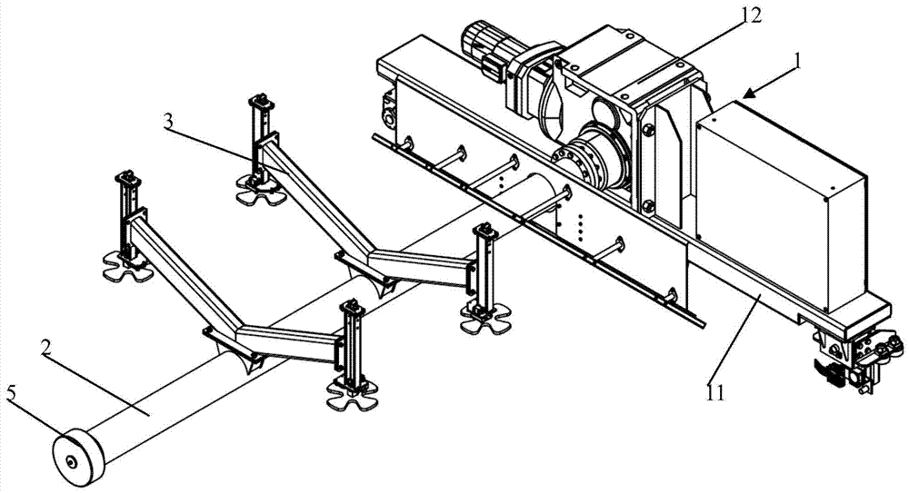
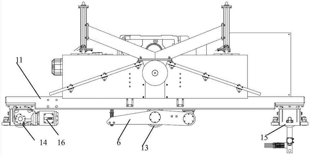
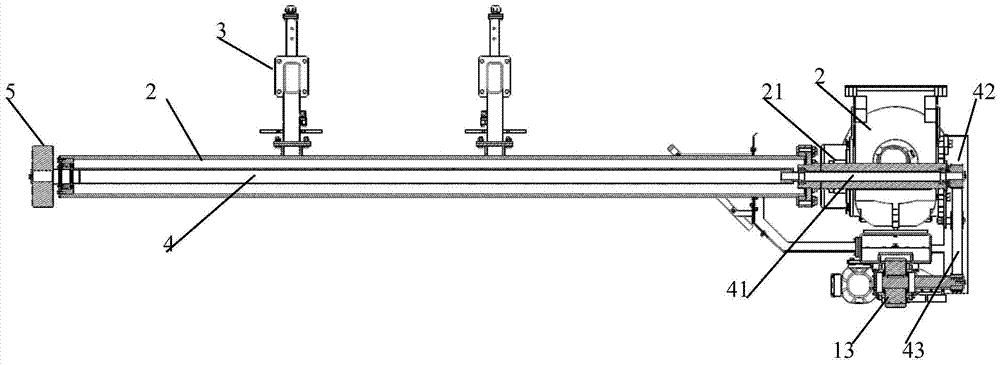
[0022] Such as Figure 1-3 As shown, a turning machine for transporting materials according to the present invention includes a transport vehicle 1 capable of walking on a track 10, a hollow transmission shaft 2 and a fixed frame 3 arranged on the transmission shaft. The transport vehicle includes a vehicle frame 11, a traveling wheel arranged at the bottom of the vehicle frame, a rotating motor fixedly arranged on the vehicle frame and a hollow shaft type speed reducer 12, and a rotatably arranged vehicle frame bottom and keeps friction with the track. Contact friction wheel 13, described traveling wheel comprises the traveling wheel 14 that is arranged on the front end of the vehic...


PUM


Abstract

The invention discloses a turnover device for conveying materials. The turnover device for conveying the materials comprises a transport cart capable of walking on a track, a hollow transmission shaft and a fixing frame arranged on the transmission shaft. The transport cart comprises a cart frame, a walking wheel arranged at the bottom of the cart frame, a rotating motor and a hollow-shaft reducer which are fixedly arranged on the cart frame and a friction wheel which can be arranged at the bottom of the cart frame in a rotating mode and is contacted with the track in a friction mode, wherein the transmission shaft is in transmission connection with the reducer. Due to adoption of the hollow-shaft reducer, the connecting mode between the transmission shaft and the reducer is simplified. The follow-up of the friction wheel can be simultaneously transmitted to a supporting wheel through the hollow transmission shaft and a linked shaft which are embedded inside and outside. Therefore, the turnover device for conveying the materials saves the driving parts of the supporting wheel, greatly reduces the cost, is strong in using synchronicity of the friction wheel, avoids the speed difference generated from the two sides of the transmission shaft and improves the stability of operation.

Description

technical field [0001] The invention relates to the technical field of painting, in particular to a turning machine for conveying materials. Background technique [0002] When painting, it is often necessary to transport materials, such as the car body forward along the track, and at the same time carry out predetermined flipping during the conveying process. For example, in the electrophoresis process of the car body, it is necessary to use a turning machine to transport it to the top of the dipping pool, and then turn it over The body is turned over into the dipping tank and stays for a predetermined time before being transported out of the dipping tank and transported to the next station. [0003] In order to achieve the above operations, Chinese patent 201180028372.X discloses a device for transporting objects to be processed, which includes at least one transport vehicle, which moves linearly along the track in the transport direction; a rotating shaft which is or may ...

Claims


Application Information

Patent Timeline
Patent Type & Authority Patents(China)
IPC IPC(8): B65G35/00B65G49/02
Inventor 戈北京高超波林涛肖辉陈勇戴旻齐江飞宋书波
Owner AUTOMOTIVE ENG CORP
Learn More