Mold structure for manufacturing precise optical lens cone

A technology of precision optics and lens barrel, which is applied in the field of mold structure for making precision optical lens barrels. It can solve problems such as appearance or performance that cannot meet market demand, achieve high coaxiality, avoid top damage, and improve stability.

Active Publication Date: 2015-08-05
UNION OPTECH
View PDF5 Cites 1 Cited by
  • Summary
  • Abstract
  • Description
  • Claims
  • Application Information

AI Technical Summary

Problems solved by technology

Therefore, the injection molded products of the traditional lens barrel mold structure cannot meet the market demand in terms of appearance and performance.

Method used


Image

  • Mold structure for manufacturing precise optical lens cone
  • Mold structure for manufacturing precise optical lens cone
  • Mold structure for manufacturing precise optical lens cone

Examples


Embodiment Construction

[0018] Below in conjunction with accompanying drawing and specific embodiment the present invention is described in further detail:

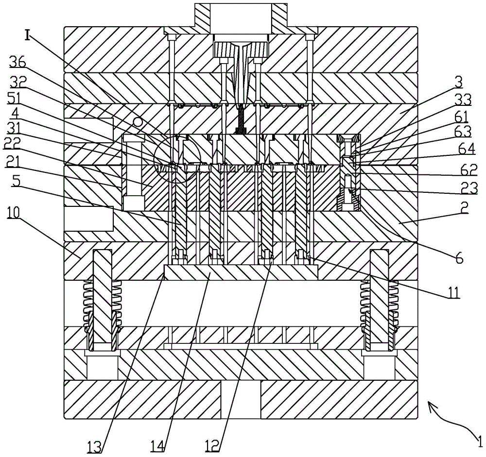
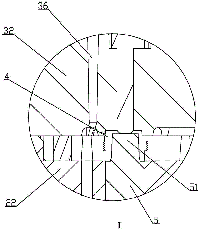
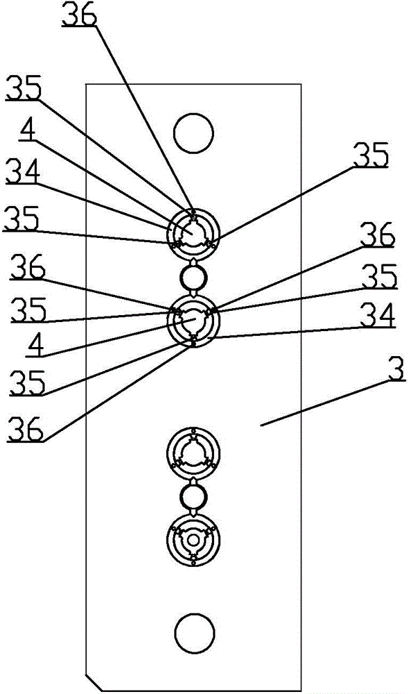
[0019] Such as Figure 1 to Figure 5 As shown, a mold structure for making a precision optical lens barrel includes a base body 1, a punch fixing plate 10, a lower mold base 2, and an upper mold base 3 are sequentially arranged on the base body 1, and a lower mold base 2 is provided with a lower mold base. Die cavity 21, the upper mold base 3 is provided with the upper mold cavity 31 that covers with the upper mold cavity 21, the lower mold cavity 21 is provided with a lower mold core 22, and the upper mold cavity 31 is provided with an upper mold core 32, convex The die fixing plate 10 is provided with a punch rod 5 that passes through the lower mold base 2 and is inserted into the lower mold core 22. The lower mold core 22, the upper mold core 32 and the punch rod 5 are surrounded by a molding cavity 4, and the lower mold core 22 A lower posi...


PUM


Abstract

The invention relates to a mold structure for manufacturing a precise optical lens cone. The mold structure comprises a base body, wherein a convex mold fixed plate, a lower mold base and an upper mold base are arranged on the base body in sequence; a lower mold cavity is formed in the lower mold base; an upper mold cavity covered with the upper mold cavity is formed in the upper mold base; a lower mold core is arranged in the lower mold cavity; an upper mold core is arranged in the upper mold cavity; the convex mold fixed plate is provided with a convex mold rod penetrating through the lower mold base to be inserted into the lower mold core; and a molding cavity is defined by the lower mold core, the upper mold core and the convex mold rod. The mold structure is characterized in that a lower positioning hole is formed in the lower mold core; the upper mold core is provided with an upper positioning hole coaxial and communicated with the lower positioning hole; and a coaxial positioning piece inserted into the upper positioning hole to penetrate through the lower mold core and the upper mold core is arranged in the lower positioning hole. The mold structure is simple in structure; and the manufactured lens cone product is high in coaxiality.

Description

【Technical field】 [0001] The invention relates to a plastic mold structure, in particular to a mold structure for making a precision optical lens barrel. 【Background technique】 [0002] The lens barrel refers to the component in which the lens is installed in the camera module of the mobile phone. The traditional mobile phone plastic lens barrel molds mostly use a large nozzle to feed the glue from the side. The plastic flow is unbalanced, and the quality of the molded lens barrel is not ideal. In addition, the lens barrel inserts are mostly processed by ordinary grinding or milling, resulting in poor size and coaxiality of each diameter of the lens barrel mounted lenses. The traditional mold structure is mostly pushed out by a push plate, and there are clamp lines on the surface of the lens barrel, which will produce burrs, which will affect the flatness of the lens barrel. As consumers have higher and higher requirements for mobile phone camera functions, the pixels of m...

Claims


Application Information

Patent Timeline
IPC IPC(8): B29C45/26B29C45/40
Inventor 赵佳岐李映强曾庆援陈远财刘有均王亚林尹鸿林邓剑明贺彦华彭清连杨勇葛承黄青邱盛平
Owner UNION OPTECH
Why Eureka
Try Eureka