Eureka AIR delivers breakthrough ideas for toughest innovation challenges, trusted by R&D personnel around the world.

Opening and closing chuck

一种卡盘、机械手的技术,应用在卡盘、夹固、支承等方向,能够解决壳体强度降低、壳体加工繁杂、活塞误动作等问题,达到机构简单的效果

Active Publication Date: 2015-08-05
SMC CORP
View PDF7 Cites 5 Cited by
  • Summary
  • Abstract
  • Description
  • Claims
  • Application Information

AI Technical Summary

Problems solved by technology

[0004] However, in such a structure that the piston and the manipulator are connected by shafts through a plurality of cutouts formed on the front surface of the housing in such a way to open and close the chuck, since the housing must be drilled, not only the housing The processing is complicated, and the strength of the housing is lowered due to the plurality of cutouts, and foreign matter such as dust enters the cylinder bore through the cutouts, so there is a problem that the piston is likely to malfunction due to the foreign matter.

Method used


Image

  • Opening and closing chuck
  • Opening and closing chuck
  • Opening and closing chuck

Examples


Embodiment Construction

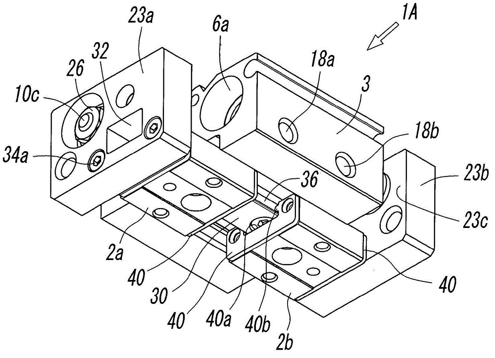
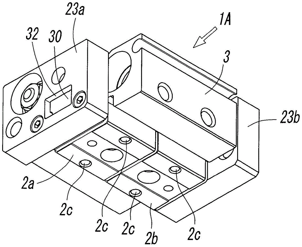
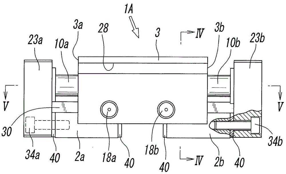
[0039] Figure 1 to Figure 7 It is a figure showing the first embodiment of the opening and closing chuck of the present invention. The opening and closing chuck 1A of the first embodiment is an asynchronous operation in which two manipulators 2a and 2b independently and asynchronously perform opening and closing operations. The opening and closing chuck of the type is an opening and closing chuck of the same thrust type in which the holding forces (thrust) acting on the above-mentioned two manipulators 2a, 2b are equal to each other.

[0040] The above-mentioned opening and closing chuck 1A has a chuck main body 3 formed as a substantially rectangular block in plan view, and inside the chuck main body 3, first and second two air cylinder devices are arranged in parallel with each other. 4a, 4b. That is, in the interior of the chuck main body 3, the first cylinder hole 6a and the second cylinder hole 6b parallel to each other are formed from the first end 3a side of the chuck...


PUM


Abstract

A guide rail is provided on an outer surface of a chuck body. A pair of fingers is disposed on the guide rail. At least one of the pair of fingers is a movable finger that is movable along the guide rail. One or two cylinder apparatuses, each of which has a rod that advances and retracts in the direction of its axial line by the action of air pressure, are provided in the chuck body. The top end of the rod extends from an end of the chuck body to the outside. An end block is attached to the top end of the rod. The end block is linked to the movable finger.

Description

technical field [0001] The present invention relates to an opening and closing chuck including a pair of manipulators that open and close a workpiece by air pressure, and more particularly, to an opening and closing chuck including a pair of manipulators that open and close by moving along guide rails. Background technique [0002] An opening and closing chuck including a pair of manipulators that open and close by moving along a guide rail is conventionally known as disclosed in Patent Document 1, for example. In this opening and closing chuck, a pair of manipulators are arranged on the front surface of the housing in a manner that can be freely opened and closed along the guide rails, and two cylinder holes are formed in parallel to the left and right inside the housing, and the The inner piston and the pair of manipulators are individually connected by a shaft, and the two pistons are operated by air pressure to open and close the pair of manipulators, and the article is ...

Claims


Application Information

Patent Timeline
Patent Type & Authority Applications(China)
IPC IPC(8): B25J15/08
CPCB23Q3/08B23B2270/027B23B2231/32B23B31/30B23B31/16287B23B2231/22B23Q7/043B25B1/18B25B5/061B25J15/0293Y10T279/1224B25J15/086
Inventor 齐藤正原耕二石桥康一郎
Owner SMC CORP
Why Eureka
Eureka Blog
Learn More