
Laser welding equipment based on gradient energy band splicing

A technology of laser welding and welding equipment, which is applied in the field of laser welding equipment based on gradual energy band splicing, can solve the problems of high energy consumption and high cost, and achieve the effects of low energy consumption, low power consumption and simple control

Inactive Publication Date: 2015-08-05
HUAZHONG UNIV OF SCI & TECH
View PDF5 Cites 3 Cited by
  • Summary
  • Abstract
  • Description
  • Claims
  • Application Information

AI Technical Summary

Problems solved by technology

[0004] Aiming at the defects of the prior art, the object of the present invention is to provide a laser welding equipment based on splicing of gradient energy bands, aiming to solve the problems of high energy consumption and high cost of the welding equipment in the prior art

Method used


Image

  • Laser welding equipment based on gradient energy band splicing
  • Laser welding equipment based on gradient energy band splicing
  • Laser welding equipment based on gradient energy band splicing

Examples


Embodiment Construction

[0031] In order to make the object, technical solution and advantages of the present invention clearer, the present invention will be further described in detail below in conjunction with the accompanying drawings and embodiments. It should be understood that the specific embodiments described here are only used to explain the present invention, not to limit the present invention.

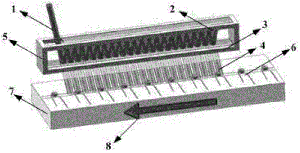
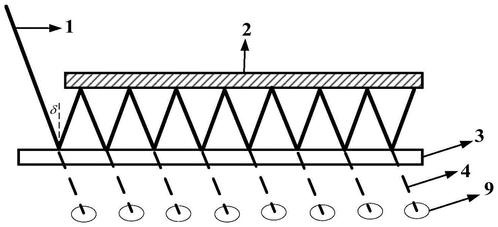
[0032] The object of the present invention is to provide a high-efficiency welding equipment for electronic components, which mainly uses the thermal radiation effect of laser to heat the electronic components, and adopts the principle that the beams are reflected multiple times in two oppositely placed reflectors, each transmission When reaching the second rectangular reflector, there will be part of the laser output, and a series of laser spots with gradually changing energy will be obtained. Soldering of quality electronic components.

[0033] The present invention skillfully utilizes two oppos...


PUM


Abstract

The invention discloses laser welding equipment based on gradient energy band splicing. The laser welding equipment comprises a laser light source, a first rectangular reflecting plate and a second rectangular reflecting plate. The first rectangular reflecting plate and the second rectangular reflecting plate are oppositely placed; the film plating is performed for the surfaces of the first reflecting plate and the second reflecting plate, so that one part of an incident beam is reflected and the other part is transmitted when the incident beam is emitted to the second rectangular reflecting plate with an incident angle delta; the transmitted part is formed to a first light spot on the welding surface; the reflected part is transmitted to the first rectangular reflecting plate for full reflecting, and is partially transmitted by the second rectangular reflecting plate to form a second light spot on the welding surface; laser is continuously reflected in a light conducting channel consisting of the first rectangular reflecting plate and the second rectangular reflecting plate; and one part of the laser is output when being transmitted to the second rectangular reflecting plate each time so as to form a series of laser light spots with different energies on the welding surface. An electronic element passes through the laser light spots with different energies to realize a needed temperature rise curve so as to finish the welding of the electronic element.

Description

technical field [0001] The invention belongs to the technical field of laser welding of electronic components, and more specifically relates to a laser welding device based on splicing of gradient energy bands. Background technique [0002] With the rapid development of the electronic and microelectronics industry, the soldering of electronic components (capacitors, resistors) and the welding of electronic components and PCBs and other related processes and equipment have become the core technology of the electronic device packaging industry, and promote the rapid development of microelectronics technology and applications. develop. [0003] According to the different welding processes of electronic components, the corresponding welding equipment is also different, from manual welding torches, wave soldering equipment, to tunnel furnaces, vacuum reflow soldering furnaces and other welding equipment can provide the required welding process to complete the corresponding electr...

Claims


Application Information

Patent Timeline
Patent Type & Authority Applications(China)
IPC IPC(8): B23K1/005B23K3/00B23K3/08
CPCB23K1/0056B23K1/0016B23K3/00B23K3/08
Inventor 朱广志朱晓周业波朱长虹王海林郭飞齐丽君
Owner HUAZHONG UNIV OF SCI & TECH
Learn More