Variable spiral continuous stirrup reinforcement frame forming machine main reinforcement bracket

A steel frame and forming machine technology, applied in the direction of metal processing equipment, etc., can solve the problems affecting the overall quality of the steel frame, bending deformation of the main reinforcement, and affecting the forming of the remaining steel frame, etc., to achieve increased adjustment adaptability, effective support, and simple structure Effect

Inactive Publication Date: 2016-08-17
SHANDONG JIANZHU UNIV
View PDF8 Cites 0 Cited by
  • Summary
  • Abstract
  • Description
  • Claims
  • Application Information

AI Technical Summary

Problems solved by technology

Due to the different cross-sectional shapes and sizes of the reinforced skeleton, and the main reinforcement is generally long, some suspended main reinforcements are prone to bending deformation during the forming process of the reinforced skeleton, and the remaining free main reinforcements will also be offset due to the stress factor of part of the formed skeleton. Thus affecting the forming of the remaining steel skeleton part, seriously affecting the overall quality of the steel skeleton after forming

Method used


Image

  • Variable spiral continuous stirrup reinforcement frame forming machine main reinforcement bracket
  • Variable spiral continuous stirrup reinforcement frame forming machine main reinforcement bracket
  • Variable spiral continuous stirrup reinforcement frame forming machine main reinforcement bracket

Examples


Embodiment Construction

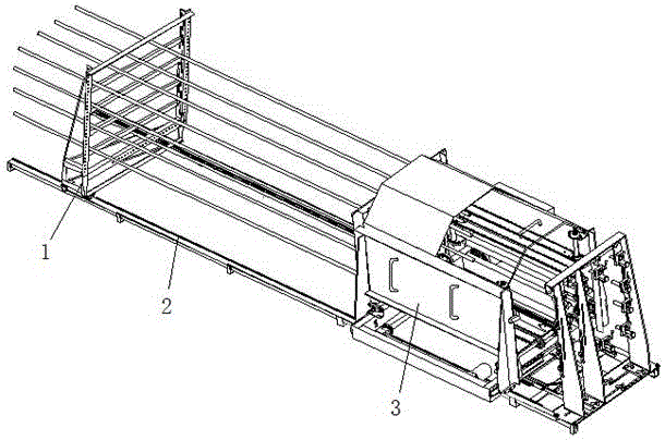
[0018] Such as image 3 As shown, the main reinforcement bracket 1 of the variable spiral continuous stirrup reinforcement skeleton forming machine of the present invention is installed on the guide rail 2 of the variable spiral continuous stirrup reinforcement reinforcement skeleton formation machine, and is located at the rear side of the stirrup box 3 to support the main reinforcement. It can be set to multiple groups according to the length of the main reinforcement.

[0019] Such as Figure 4 As shown, the main reinforcement bracket 1 is mainly composed of a walking frame 4. The walking frame 4 is provided with a roller 5 and several brackets 6 for supporting the main reinforcement. The guide rail 2 fits. The walking frame 4 also includes a main frame and a movable adjustment frame; the main frame is composed of a fixed vertical adjustment frame 9, a fixed horizontal adjustment frame 14 and a balance frame 7, and the three are vertically intersected, wherein the two ver...


PUM


Abstract

Disclosed is a main rebar bracket of a variable spiral continuous stirrup rebar framework forming machine. The main rebar bracket mainly comprises a travelling frame, wherein rolling wheels and a plurality of supporting fork portions are arranged on the travelling frame, the supporting fork portions are used for supporting main rebars, and the rolling wheels are matched with horizontally-laid guide rails of the rebar framework forming machine. The travelling frame further comprises a main frame and a movable adjusting frame. The main frame comprises a fixed vertical adjusting frame, a fixed transverse adjusting frame and a balancing frame, wherein the fixed vertical adjusting frame, the fixed transverse adjusting frame and the balancing frame perpendicularly intersect. The movable adjusting frame comprises a movable vertical adjusting frame and a movable transverse adjusting frame. A plurality of slideways and adjusting holes are formed in the fixed vertical adjusting frame, and a plurality of adjusting holes are formed in the fixed transverse adjusting frame. A plurality of slideways and adjusting holes are formed in the movable vertical adjusting frame, and correspond to the slideways and the adjusting holes formed in the fixed vertical adjusting frame in a one-to-one mode, and a plurality of adjusting holes are formed in the movable transverse adjusting frame, and correspond to the adjusting holes formed in the fixed transverse adjusting frame in a one-to-one mode. The main rebar bracket is simple in structure and can conduct adjustment and supporting according to the arrangement conditions of the main rebars.

Description

technical field [0001] The invention belongs to the technical field of steel bar frame forming construction in the construction industry, and in particular relates to a main bar bracket of a variable spiral continuous stirrup bar frame forming machine. Background technique [0002] Existing steel bar skeleton forming equipment welds a plurality of circular or square main bars A1 and one-way spiral stirrups A2 wound on the main bars A1 to form such figure 1 The steel frame A shown. A steel cage forming machine is disclosed in the Chinese invention patent application publication CN104096786A. This technology can manufacture a steel cage for reticular spiral stirrups, but the steel skeleton of the above-mentioned unidirectional spiral stirrups or reticular spiral stirrups, the stirrups The reinforcement is only wound around the outer circumference of the main reinforcement, and it is difficult to process a steel skeleton with inner stirrups or coexistence of inner and outer st...

Claims


Application Information

Patent Timeline
Patent Type & Authority Patents(China)
IPC IPC(8): B21F33/00
Inventor 张明勤马荣全姚玉善苗冬梅原政军孟宪举王晴郝圣文金钢韩立芳
Owner SHANDONG JIANZHU UNIV
Why Eureka
Try Eureka