Wire fixing jig

A technology for fixing jigs and wires, which is applied in the direction of sensors and electrical components, can solve the problems of affecting the production efficiency of earphones, prone to pinching or pinching, unfavorable assembly line operations, etc., and achieves small deformation, simple structure, and reliable fixation Effect

Active Publication Date: 2015-07-29
GOERTEK INC
View PDF5 Cites 2 Cited by
  • Summary
  • Abstract
  • Description
  • Claims
  • Application Information

AI Technical Summary

Problems solved by technology

[0004] 1. The part where the wire is clamped by the clip is prone to pinching or pinching, resulting in poor appearance of the wire and reducing the qualified rate of the product
[0005] 2. During the production and proce...

Method used


Image

  • Wire fixing jig
  • Wire fixing jig
  • Wire fixing jig

Examples


Embodiment Construction

[0032] Below in conjunction with accompanying drawing and embodiment, further elaborate the present invention.

[0033] The longitudinal direction referred to in this specification refers to the extending direction of the wiring substrate and the wiring substrate, and the transverse direction refers to the direction perpendicular to the extending direction of the wiring substrate and the wiring substrate.

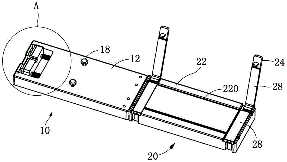
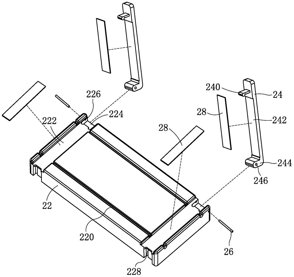
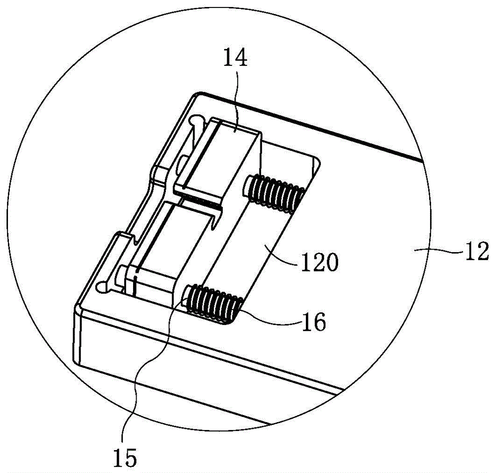
[0034] Such as figure 1 As shown, a wire fixing jig includes a wire assembly 10 and a clamping assembly 20 connected together. The wire assembly 10 includes a rectangular wire substrate 12. The wire clamping assembly 20 includes a rectangular wire clamping substrate 22. The wire substrate 12 is consistent with the width of the wiring substrate 22, and one end of the wiring substrate 12 is connected to one end of the wiring substrate 22, that is, the short side of one side of the wiring substrate 12 is connected to the short side of one side of the wiring substrate 22, so t...


PUM


Abstract

The invention discloses a wire fixing jig, and relates to the technical field of wire processing molds. The wire fixing jig comprises a wire guide assembly and a wire clamp assembly. The wire guide assembly and the wire clamp assembly are connected with each other, the wire guide assembly comprises a wire guide base plate, the wire clamp assembly comprises a wire clamp base plate, and one end of the wire guide base plate is connected with an end of the wire clamp base plate; a slider is slidably mounted at the other end of the wire guide base plate, the sliding direction of the slider is consistent with the extending direction of the wire guide base plate, a clamp portion which is used for clamping a wire distributor for wires is arranged on the slider, and at least two wire distributing columns are arranged in the middle of the wire guide base plate; two wire clamp plates are respectively hinged to two ends of the wire clamp base plate, and the wires can be clamped between the wire clamp base plate and the wire clamp plates by the two wire clamp plates. The wire fixing jig has the advantages that the wire fixing jig is simple in structure and convenient to use, and the wires can be reliably fixed by the aid of the wire fixing jig and can be prevented from being damaged; the wire fixing jig is suitable for assembly line work, and the production efficiency of products can be effectively improved.

Description

technical field [0001] The invention relates to the technical field of wire rod processing molds, in particular to a wire rod fixing jig. Background technique [0002] Along with the continuous development of electronic technology, there are more and more types of portable electronic devices capable of playing audio signals, such as MP3 (music player), mobile phone and PAD (tablet computer), etc., and applications are becoming more and more popular. The earphone can directly transmit the sound from the above-mentioned various electronic devices to the user's ear, avoiding the influence of the external noisy environment on the listening effect, providing the user with a high-quality sound signal, and at the same time will not interfere with other surrounding People, just because the earphone has the above-mentioned advantages, the earphone has become an indispensable accessory for the above-mentioned various electronic devices. [0003] The structure of the earphone usually ...

Claims


Application Information

Patent Timeline
IPC IPC(8): H04R31/00
Inventor 姬常超赵善永杜刚
Owner GOERTEK INC
Why Eureka
Try Eureka