


Quick Research
Generate reliable direction feasibility study reports for your R&D in just a few steps.

Technical Q&A
Discover and master advanced knowledge NOW. Basics, ideas, possibilities, all at once.

Find Solutions
As an expert in R&D theories, this can generate solutions to your technical problems instantly.

Evaluate Feasibility
Analyze your overall solution with one click, know your potential R&D risks in advance.

Monitor Landscape
Get weekly tech updates, stay abreast of the latest tech innovations and key insights.
Electric apparatus and residual electric charge discharging method
A technology for electrical devices and residual charges, applied to electrical components, electrical recording technology using charge patterns, equipment using electrical recording technology using charge patterns, etc., can solve the problems of not considering the residual charge of the power circuit and the inability to prevent inrush current, etc.
- Summary
- Abstract
- Description
- Claims
- Application Information
AI Technical Summary
Problems solved by technology
Method used
Image

Examples
Embodiment approach 1
[0038] This embodiment shows a basic form of a power supply circuit having a discharge circuit for discharging the residual charge of each of the power supply circuit and the load circuit when the relay is turned off to cut off the power supply.
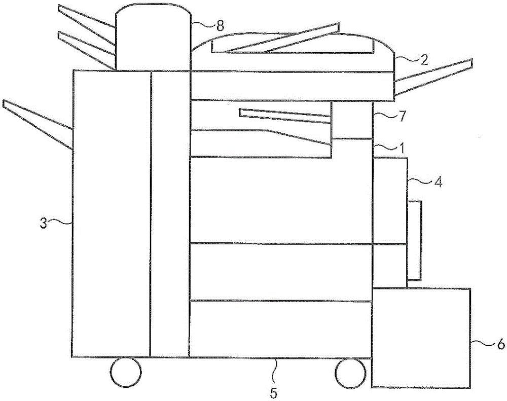
[0039] figure 2 is the image forming apparatus of this embodiment (see figure 1 ) is a schematic diagram of the circuit structure for supplying power to a load via an on / off controllable relay.
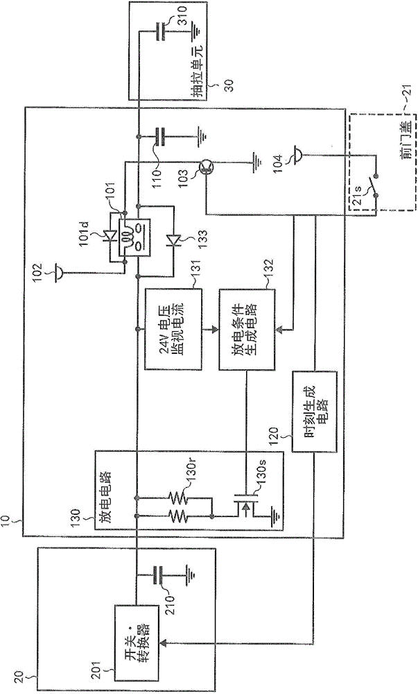
[0040] Such as figure 2As shown, the power supply 20 incorporates a power conditioner and has a switch / converter 201 for outputting DC power. The power supply 20 also has a capacitive element 210 .
[0041] The pull unit 30 is a load circuit that requires power. The circuit of the drawing unit 30 has a capacitive element 310 . The circuit board 10 of the power supply circuit is provided with a capacitor 110, which is connected in parallel with the pull unit 30 as a load circuit, and is a capacitive element for stabilizing power supply...
Embodiment approach 2
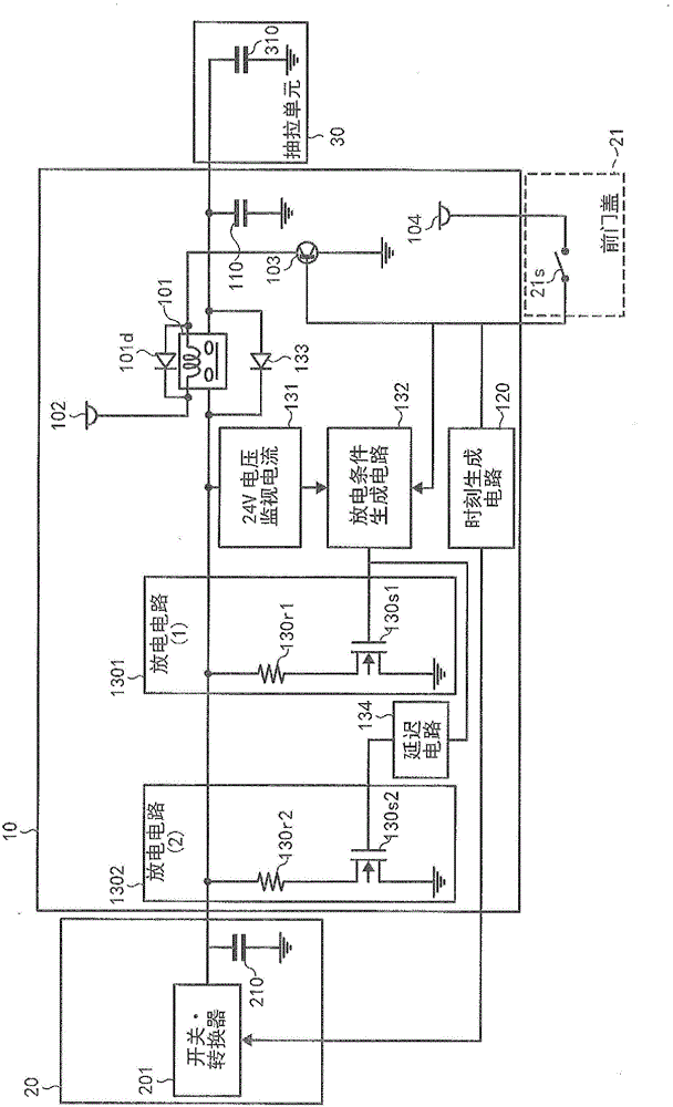
[0072] This embodiment is a modification of the discharge circuit in the power supply circuit of Embodiment 1 described above as the basic form.
[0073] figure 2 The discharge circuit 130 in the power supply circuit according to Embodiment 1 is configured such that a resistor 130r on the power supply line on the input side of the relay 101 is connected to a FET 130s for switching with the output terminal of the relay 130 as GND.
[0074] exist figure 2 In the illustrated embodiment, the discharge circuit is formed with a resistor 130r and a FET 130s. Therefore, according to the difference in the amount of residual charge when the relay is turned off, the voltage level when discharging through the resistor 130r and the FET 130s is also different. When the amount of residual charge reaches the maximum, a large voltage is applied to the impedance 130r and the FET 130s, and the discharge current during discharge is also large.
[0075] For this reason, it is necessary to sel...
Embodiment approach 3
[0094] This embodiment changes the circuit for controlling the ON / OFF of the relay in the power supply circuit of the above-mentioned Embodiment 1 as a basic mode.
[0095] exist figure 2 In the power supply circuit of Embodiment 1 shown, the circuit for controlling the on / off of the relay 101 controls the on / off of the relay 101 by interlocking with the closing / unlocking of the front door cover 21 .
[0096] The interlock switch 21s is opened and closed according to the locking / opening of the front door cover 21, and accordingly, the transistor 103 performs switching operation on / off, and guides whether the relay 101 performs the driving operation of the electromagnetic coil, thereby turning on / off the relay. In short, the on / off of the relay 101 is linked to the manual locking / unlocking of the front door cover 21 .
[0097] figure 2 In the power supply circuit shown, the power supply from the switch / converter 201 of the power supply 20 to the circuit board 10 of the powe...
PUM
 Abstract
Description
Claims
Application Information
 - R&D Engineer
- R&D Manager
- IP Professional
- Industry Leading Data Capabilities
- Powerful AI technology
- Patent DNA Extraction
Browse by: Latest US Patents, China's latest patents, Technical Efficacy Thesaurus, Application Domain, Technology Topic, Popular Technical Reports.
© 2024 PatSnap. All rights reserved.Legal|Privacy policy|Modern Slavery Act Transparency Statement|Sitemap|About US| Contact US: help@patsnap.com