Light guide plate and backlight module

A technology of light guide plate and light guide part, which is applied in the direction of light guide, optics, optical components, etc., can solve the problems of excessive loss of light, reduce light utilization rate, and difficulty in achieving light coupling efficiency, so as to improve light coupling efficiency and benefit Thin design, the effect of improving light utilization

Active Publication Date: 2015-07-29
WUHAN CHINA STAR OPTOELECTRONICS TECH CO LTD
View PDF3 Cites 7 Cited by
  • Summary
  • Abstract
  • Description
  • Claims
  • Application Information

AI Technical Summary

Problems solved by technology

[0007] However, with the deepening of the thinning of the light guide plate, the thickness of the light guide part of the light guide plate becomes thinner and thinner, and the thickness difference between the light incident part and the light guide part of the light guide plate becomes larger, such as figure 2 As shown, the inclination of the first slope 220 becomes larger, so that part of the light with a large angle cannot enter the interior of the light guide plate for recycling, thereby reducing the utilization rate of the light.
In backlight modules that are getting thinner and thinner, more light is lost at the light incident part of the light guide plate, and part of the light will become stray light and enter the optical film area above the light guide plate, resulting in bright edges
Therefore, it is difficult to achieve the ideal light coupling efficiency only by setting the light incident part with a wedge structure in the light guide plate

Method used


Image

  • Light guide plate and backlight module
  • Light guide plate and backlight module
  • Light guide plate and backlight module

Examples


Embodiment Construction

[0031] In order to further explain the technical means adopted by the present invention and its effects, the following describes in detail the preferred embodiments of the present invention and the accompanying drawings.

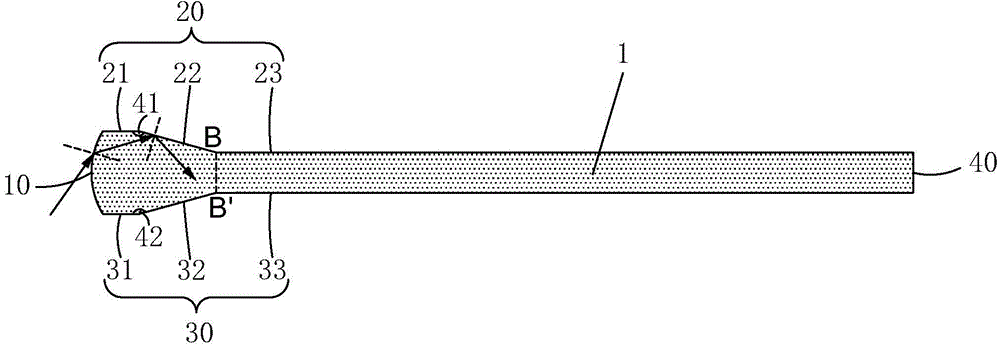
[0032] See image 3 , The present invention provides a light guide plate 1, which has a first end surface 10, a second end surface 40 corresponding to the first end surface 10, and an upper surface connecting the upper ends of the first end surface 10 and the second end surface 40 respectively 20. And the lower surface 30 respectively connecting the lower ends of the first end surface 10 and the second end surface 40;

[0033] Specifically, the upper surface 20 is composed of three parts, namely a first horizontal plane 21, a first inclined plane 22, and a second horizontal plane 23; the first horizontal plane 21 is connected to the first end surface 10, and the first inclined plane 22 is connected at an inclination between the first horizontal plane 21 and the s...


PUM


Abstract

The invention provides a light guide plate and a backlight module. The light inlet surface of the light guide plate is arc-shaped; a first inclined surface and a second inclined surface are respectively arranged on the side, close to the light inlet surface, of the upper surface and the lower surface of the light guide plate, so that light at a large angle can be totally reflected at the first inclined surface and the second inclined surface after the gathering action of the arc-shaped light inlet surface, and enter the light guide plate; the light which enters the light guide plate is emitted out from a light outlet surface after being transferred and reflected; the light utilization rate is improved; the light coupling efficiency is improved. The light guide plate of the structure has a good converging effect on the light at various angles, so that the thickness of a light guide part of the light guide plate can be reduced without losing the light coupling efficiency; the thin-type design of the light guide plate is facilitated. The backlight module provided by the invention adopts the light guide plate of the special structure, so that the backlight module has a smaller thickness and a better light outlet effect.

Description

Technical field [0001] The invention relates to the field of display technology, in particular to a light guide plate and a backlight module. Background technique [0002] Liquid Crystal Display (LCD) has many advantages such as thin body, power saving, and no radiation, and has been widely used, such as: mobile phones, personal digital assistants (PDA), digital cameras, computer screens or notebook computers Screen etc. [0003] Most of the liquid crystal display devices currently on the market are backlight liquid crystal display devices, which include a casing, a liquid crystal panel arranged in the casing, and a backlight module arranged in the casing. The structure of a traditional liquid crystal panel is composed of a color filter substrate (Color Filter), a thin film transistor array substrate (Thin Film Transistor Array Substrate, TFT Array Substrate), and a liquid crystal layer (Liquid Crystal Layer) disposed between the two substrates. The working principle of the struc...

Claims


Application Information

Patent Timeline
Patent Type & Authority Applications(China)
IPC IPC(8): G02B6/00G02F1/13357
CPCG02B6/0013G02B6/0018G02B6/002G02F1/133606G02F1/133607G02B6/0088
Inventor 郭伟曾杰周革革
Owner WUHAN CHINA STAR OPTOELECTRONICS TECH CO LTD
Why Eureka
Try Eureka