
Anti-islanding protection testing circuit and method based on constant impedance load simulation

A technology of constant impedance load and test circuit, which is applied in the direction of measuring electricity, measuring electrical variables, measuring devices, etc., which can solve the problem that the shape of the device is too large, the feedback energy cannot be realized, and the anti-islanding protection test of grid-connected photovoltaic inverters can be carried out. problem, to achieve the effect of compact device shape, quick splicing, and easy anti-islanding protection test work.

Active Publication Date: 2015-07-29
STATE GRID CORP OF CHINA +3
View PDF6 Cites 14 Cited by
  • Summary
  • Abstract
  • Description
  • Claims
  • Application Information

AI Technical Summary

Problems solved by technology

[0004] In order to solve the problem of testing and verifying the anti-islanding protection function of grid-connected photovoltaic inverters based on the scheme based on adjustable RLC load, the present invention has the problem that the appearance of the device is too large, a high-power fan is required for heat dissipation, and feedback energy saving and long-term operation adjustment cannot be realized. Aiming at the problem of decreased accuracy and the difficulty of carrying out the anti-islanding protection test of grid-connected photovoltaic inverters at the site where distributed photovoltaic power generation is connected, an anti-islanding protection test circuit based on constant impedance load simulation is proposed

Method used


Image

  • Anti-islanding protection testing circuit and method based on constant impedance load simulation
  • Anti-islanding protection testing circuit and method based on constant impedance load simulation
  • Anti-islanding protection testing circuit and method based on constant impedance load simulation

Examples


Embodiment Construction

[0015] The present invention will be further described below in conjunction with the accompanying drawings and specific embodiments.

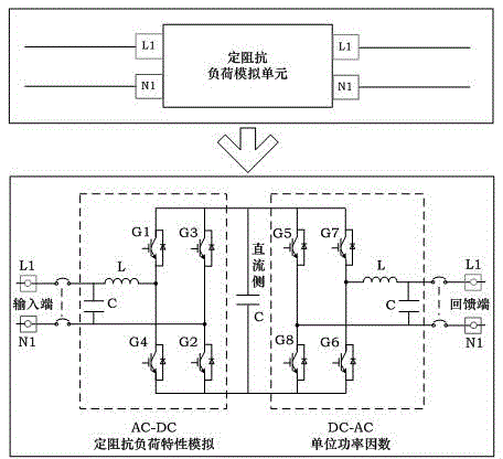
[0016] Referring to Figure 1, the present invention provides an anti-islanding protection test circuit based on constant impedance load simulation, the test circuit includes a constant impedance load simulation unit, a monitoring unit and a measurement unit; the first input terminal of the measurement unit is connected to the grid-connected photovoltaic The output of the inverter; the second input terminal of the measurement unit is connected to the first output terminal of the monitoring unit; the first output terminal of the measurement unit is connected to the constant impedance load simulation unit; the constant impedance load simulation The first output of the unit is connected to the distribution network; the second output of the constant impedance load simulation unit is connected to the second input of the monitoring unit; the bypass swi...


PUM


Abstract

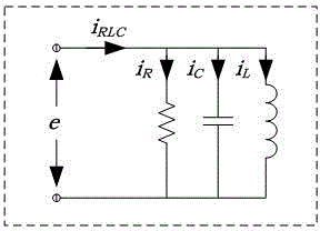
The invention aims to provide an anti-islanding protection testing circuit based on constant impedance load simulation; the circuit comprises a constant impedance load simulation unit, a monitoring unit and a measuring unit; the input end of the measuring unit is connected with the output end of a grid-connected photovoltaic inverter; the first output end of the measuring unit is connected with a 0.4kV power distribution network; a bypass switch is connected between the input end of the constant impedance load simulation unit and the first output end in parallel; the first input end of the monitoring unit is connected with the second output end of the measuring unit; the second input end of the monitoring unit is connected with the output end of the constant impedance load simulation unit; the third input end of the monitoring unit is connected with the second output end of the bypass switch. The constant impedance load simulation unit accurately simulates load characteristics of a parallel RLC (radio link control) load and feeds an active power output by the grid-connected photovoltaic inverter to the power distribution network in a unit power factor, so that the anti-islanding protection of the grid-connected photovoltaic inverter is enabled to be triggered in testing process; the circuit and the method disclosed by the invention have the advantages of no obvious heating, compact device and the like.

Description

technical field [0001] The invention relates to a test circuit, in particular to an anti-islanding protection test circuit based on constant impedance load simulation. Background technique [0002] With the large number of distributed photovoltaic power sources connected to the distribution network, the possibility of unplanned islands also increases. If an unplanned island occurs, the "reverse power transmission" of distributed photovoltaic power generation will seriously threaten the safety of power operation and maintenance personnel. The distributed photovoltaic power supply is connected to the grid through the inverter interface. In order to prevent unplanned islanding, the grid-connected photovoltaic inverter must be equipped with an anti-islanding protection function. At present, the scheme based on adjustable RLC load is widely used to test and verify the anti-islanding protection function of grid-connected photovoltaic inverters. The device is too large, requires a...

Claims


Application Information

Patent Timeline
IPC IPC(8): G01R31/00
Inventor 范元亮陈彬郑高
Owner STATE GRID CORP OF CHINA
Learn More