
Pneumatic sensor

A pneumatic sensor and sensor unit technology, applied in the field of sensors, can solve the problems of being susceptible to external vibration interference, high requirements for external signal processing circuits, and small output signals, and achieve low production costs, low requirements, and large output signals.

Active Publication Date: 2015-07-29
NEWNAGY TANGSHAN
View PDF9 Cites 8 Cited by
  • Summary
  • Abstract
  • Description
  • Claims
  • Application Information

AI Technical Summary

Problems solved by technology

[0003] The purpose of the invention is to provide a pneumatic sensor aimed at the defects of the prior art, which is used to solve the problems of the prior art that the output signal of the pneumatic sensor is small, the requirements for the external signal processing circuit are high, and it is easily disturbed by external vibrations.

Method used


Image

  • Pneumatic sensor
  • Pneumatic sensor
  • Pneumatic sensor

Examples


Embodiment Construction

[0058] In order to fully understand the purpose, features and effects of the present invention, the present invention will be described in detail through the following specific embodiments, but the present invention is not limited thereto.

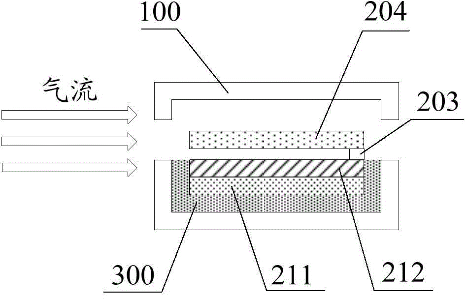
[0059] The present invention provides a pneumatic sensor, which comprises: a shielding shell, an insulating layer arranged on part or all of the inner surface of the shielding shell, and at least one sensing unit. At least two air vents are opened on the shielding shell, and the air flow passes between the air vents. The sensing unit includes: at least one fixed layer and one free layer. At least one fixed layer is fixed on the shielding shell. The free layer has a fixed part and a friction part, the fixed part of the free layer is fixedly connected with at least one fixed layer or the shielding shell, and the free layer rubs against at least one fixed layer and / or the shielding shell through the friction part. Wherein, at least one fixe...


PUM


Abstract

The invention discloses a pneumatic sensor, which comprises a shielding shell, an insulating layer arranged at part or all of the inner side surface of the shielding shell and at least one sensing unit, wherein the shielding shell is provided with at least two air vents, and an air flow passes through a part between the air vents; the sensing unit comprises at least one fixed layer and a free layer; the at least one fixed layer is fixedly arranged on the shielding layer; the free layer is provided with a fixed portion and a friction portion; the fixed portion of the free layer is fixedly connected with the at least one fixed layer or the shielding shell; the free layer is in friction with the at least one fixed layer and / or the shielding shell through the friction portion; and the at least one fixed layer and / or the shielding layer are / is a signal output end of the pneumatic sensor. The pneumatic sensor is low in manufacturing cost, great in output signal, low in requirement for an external signal processing circuit and reduces interference imposed on the pneumatic sensor by external vibration.

Description

technical field [0001] The invention relates to the technical field of sensors, in particular to a pneumatic sensor. Background technique [0002] With the continuous development of technology and people's living needs, pneumatic sensors have been applied in many aspects of life. However, the existing pneumatic sensors have the problems of high manufacturing cost, complex manufacturing process, small output signal, high requirements for external signal processing circuits, and are easily disturbed by external vibrations. Contents of the invention [0003] The purpose of the present invention is to provide a pneumatic sensor for the defects of the prior art, which is used to solve the problems of the prior art that the output signal of the pneumatic sensor is small, the requirements for the external signal processing circuit are high, and it is easily disturbed by external vibrations. . [0004] The invention provides a pneumatic sensor, comprising: a shielding shell, an ...

Claims


Application Information

Patent Timeline
IPC IPC(8): G01D5/42
Inventor 孙利佳林同福赵豪徐传毅
Owner NEWNAGY TANGSHAN
Learn More