A method for measuring the non-orthogonality of the guide rail of a long-distance motor
A non-orthogonal, long-distance motor technology, applied in the direction of measuring devices, instruments, optical devices, etc., can solve the problems that the code ruler and the guide rail cannot guarantee absolute parallelism, follow the change, and the accuracy is limited.
- Summary
- Abstract
- Description
- Claims
- Application Information
AI Technical Summary
Problems solved by technology
Method used
Image

Examples
Embodiment 1
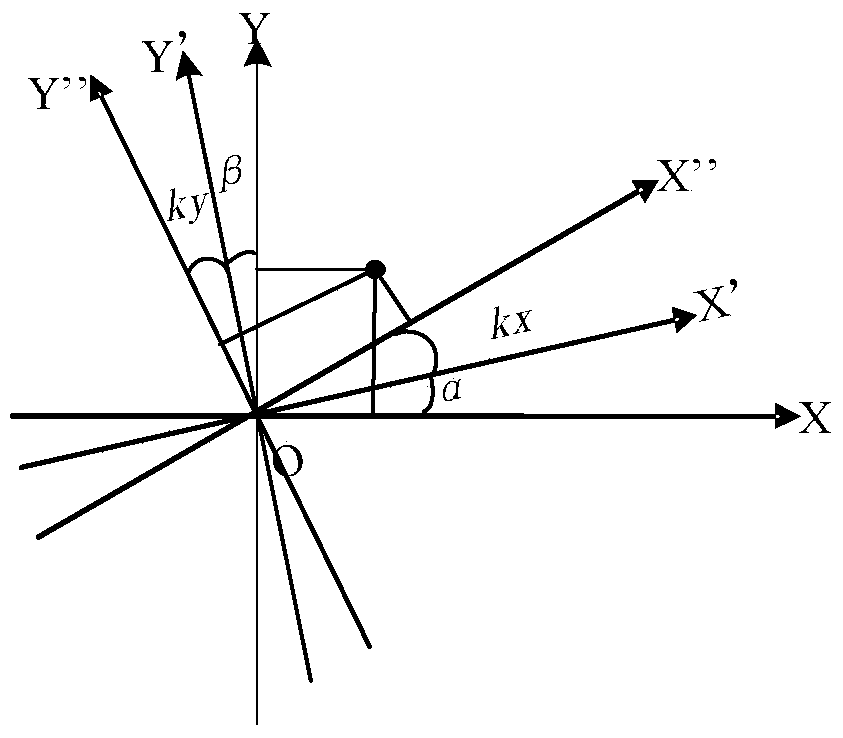
[0075] When the positioning platform has two sets of measurement systems: an interferometer and a code ruler, embodiment 1 illustrates how to use the interferometer as a reference to measure the deviation between the code ruler coordinate system and the interferometer coordinate system, namely figure 1 kx and ky, and the scale coefficients sx (X direction) and sy (Y direction) of the code ruler relative to the interferometer.
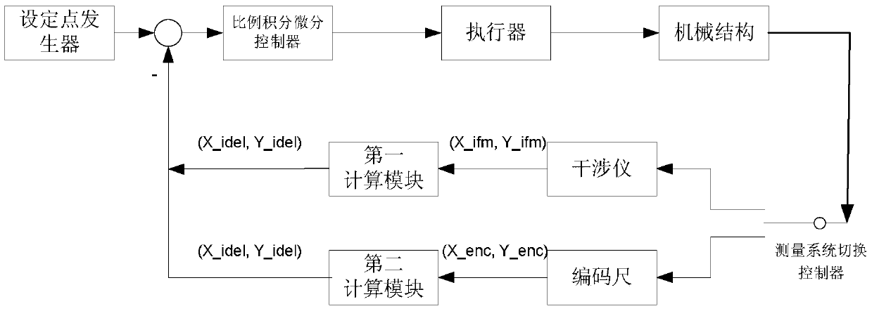
[0076] Such as image 3 As shown, it is a schematic diagram of the control loop of the positioning platform. In the figure, the set point generator, PID control module, actuator, mechanical structure, and measurement system switching controller are connected in sequence, and then different measurement systems are selected to participate in servo control according to needs. Connect the interferometer measurement system and the code ruler measurement system respectively, and finally add a calculation module after the output of the measurement system to co...
Embodiment 2
[0118] In embodiment 1, it is described that when the positioning platform has both an interferometer and a code ruler, and in embodiment 2, when the measuring system of the positioning platform has no interferometer but only a code ruler, the standard measuring tool will be used as a reference , to realize the guide rail calibration of the long-distance motor. In this embodiment, the positioning platform is a workpiece platform, and the standard measuring tool adopts alignment marks on a reference plate, and the reference plate is relatively fixed to the workpiece platform.
[0119] Specific steps are as follows:
[0120] Step 1: If Image 6 As shown, at first, at least one row of X-direction alignment marks and one column of Y-direction alignment marks are arranged on the positioning table reference plate, wherein the spacing between the marks is preset, that is to say, the nominal position of the marks (Xx mark ,Xy mark ), (Yx mark ,Yy mark ) is known.
[0121] Step 2...
Embodiment 3
[0137] Embodiment 3 is to describe that when the positioning stage has only one direction (assumed to be Y direction) long-distance motor (without interferometer measurement system), such as a mask stage, then it only needs to move on the reticle or mask stage along its moving direction It is sufficient to process a row of marks on the reference plate, and the marks are relatively fixed to the mask table. Similarly, this row of marks is the standard measuring tool, which is used as a reference to realize the guide rail calibration of the long-distance motor, such as Figure 7 shown.
[0138] Specific steps are as follows:
[0139] Step 1: first arrange at least one row of Y-direction alignment marks on the reticle or the mask table reference plate, wherein the spacing between the marks is preset, that is to say, the nominal positions of the marks (Yx mark ,Yy mark ) is known.
[0140] Step 2: Set the degrees of freedom other than X and Y to zero. Through the measurement of...
PUM
 Abstract
Description
Claims
Application Information
 - R&D
- Intellectual Property
- Life Sciences
- Materials
- Tech Scout
- Unparalleled Data Quality
- Higher Quality Content
- 60% Fewer Hallucinations
Browse by: Latest US Patents, China's latest patents, Technical Efficacy Thesaurus, Application Domain, Technology Topic, Popular Technical Reports.
© 2025 PatSnap. All rights reserved.Legal|Privacy policy|Modern Slavery Act Transparency Statement|Sitemap|About US| Contact US: help@patsnap.com