
Ring Lime Shaft Kiln

A lime and shaft kiln technology, applied in lime production and other directions, can solve the problems of energy saving, calcination uniformity and efficiency to be improved, etc., and achieve the effects of convenient multi-faceted calcination, safe operation and high production efficiency

Active Publication Date: 2016-09-07
山东万方窑炉工程科技有限责任公司
View PDF6 Cites 1 Cited by
  • Summary
  • Abstract
  • Description
  • Claims
  • Application Information

AI Technical Summary

Problems solved by technology

Although the double-fired sleeve lime kiln adopts a sleeve structure and has many advantages, it still needs to be improved in terms of energy saving, calcination uniformity and efficiency.

Method used


Image

  • Ring Lime Shaft Kiln
  • Ring Lime Shaft Kiln
  • Ring Lime Shaft Kiln

Examples


Embodiment Construction

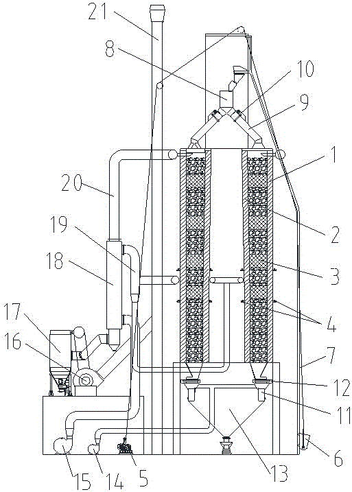
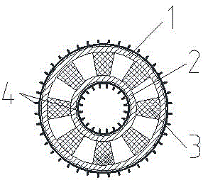
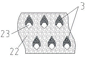
[0024] figure 1 The overall structure of the gas calcined annular lime shaft kiln of the present invention is provided, mainly including the kiln body, and the cross-sectional structure of the kiln body is as follows: figure 2 shown. The kiln body is composed of an outer ring wall 1 and an inner ring wall 2. The inner ring wall 2 is set inside the outer ring wall 1, and an annular cavity is formed between the two. In the annular cavity, a connecting outer ring wall is arranged from top to bottom. 1 and the multi-layer (2-6 layers) lintel 3 of the inner ring wall 2, the material (limestone) falls and resides in the annular cavity with the lintel. The arrangement of the lintel 3 is as follows image 3 As shown, the structure of the lintel 3 is as Figure 4 As shown, there is a cavity at the bottom. Both the inner wall of the outer ring wall 1 and the outer wall of the inner ring wall 2 are provided with refractory linings. The annular cavity is divided into a preheating zo...


PUM

PropertyMeasurementUnit
heightaaaaaaaaaa

Abstract

The invention discloses an annular lime shaft kiln. The annular lime shaft kiln comprises kiln bodies, wherein each kiln body consists of an outer ring wall and an inner ring wall, an annular cavity is formed between the inner ring wall and the outer ring wall, lintels through which the outer ring wall and the inner ring wall are connected are arranged in the annular cavity, the annular cavity is divided into a preheating zone, a calcining zone and a cooling zone from up to down, and burner nozzles are respectively arranged at the parts at the calcining zone of the outer ring wall and the inner ring wall; a distribution mechanism is arranged at the upper ends of the annular cavities, a discharging mechanism is arranged at the bottoms of the annular cavities, a feeding mechanism, a combustion supporting mechanism, a cooling mechanism and a waste-gas dust-removal system are arranged on the outer sides of the inner ring walls and the outer ring walls. The annular lime shaft kiln adopts annular structures of the inner ring walls and the outer ring walls, so that the air in the kiln bodies can be uniformly distributed, limestone can be uniformly calcined in a plurality of directions, and the phenomenon that limestone is stuck is avoided; the annular lime shaft kiln has the characteristics of being high in production efficiency, low in energy consumption, environment-friendly, safe in running, simple to operate, small in occupied area, low in investment, and the like.

Description

technical field [0001] The invention relates to equipment for calcining limestone to generate quicklime, and belongs to the technical field of lime burning equipment. Background technique [0002] Quicklime is produced by calcining limestone. The traditional production process is to load limestone and fuel into a lime kiln (if the gas fuel is fed through a pipeline and a burner), preheat it to 850 degrees and start to decompose, and complete calcination at 1200 degrees. After cooling , unloaded out of the kiln. Lime kiln is mainly composed of kiln body, feeding device, material distributing device, combustion device, ash unloading device, dust removal device and electric control device. The most common application is the shaft kiln. The utilization factor of ordinary shaft kiln is below 50%, the energy consumption is high, and the production efficiency is low. [0003] Therefore, some lime kilns with higher production efficiency have appeared, such as the "single-chamber ...

Claims


Application Information

Patent Timeline
Patent Type & Authority Patents(China)
IPC IPC(8): C04B2/12
CPCY02P40/40
Inventor 张玉宝吴波徐鹏姜海高勇杨艳郭玉刚
Owner 山东万方窑炉工程科技有限责任公司
Learn More