
A double-spindle turning-milling compound machine tool with inclined bed

A compound machine tool and double-spindle technology, applied in the field of CNC machine tools, can solve the problems of inability to automate two-end processing, achieve the effect of reducing production auxiliary time, reducing manufacturing cycle and waiting time, and having a wide range of applications

Active Publication Date: 2017-07-11
广东中聪智能装备有限公司
View PDF8 Cites 0 Cited by
  • Summary
  • Abstract
  • Description
  • Claims
  • Application Information

AI Technical Summary

Problems solved by technology

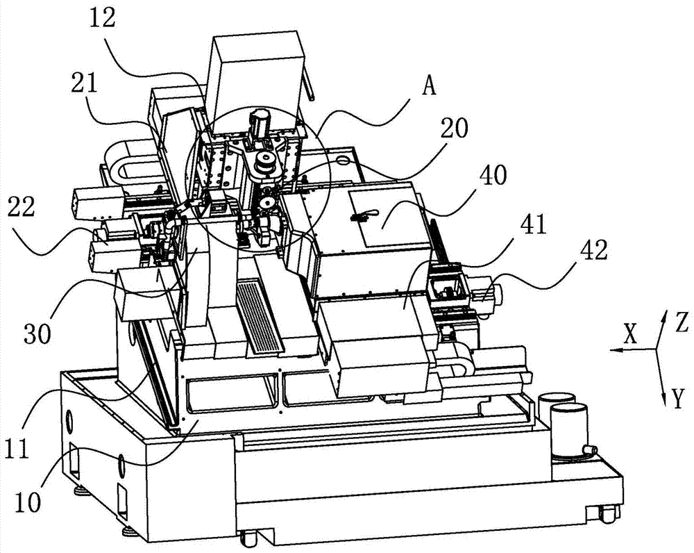
[0004]In the prior art, the turning and milling machining center only includes the main shaft for fixing the workpiece, and the processing device for processing the workpiece. When in use, one main shaft and one phase The corresponding processing device requires multiple manual operations to clamp the workpiece up and down, and cannot automatically process both ends of a workpiece

Method used


Image

  • A double-spindle turning-milling compound machine tool with inclined bed
  • A double-spindle turning-milling compound machine tool with inclined bed
  • A double-spindle turning-milling compound machine tool with inclined bed

Examples


Embodiment 1

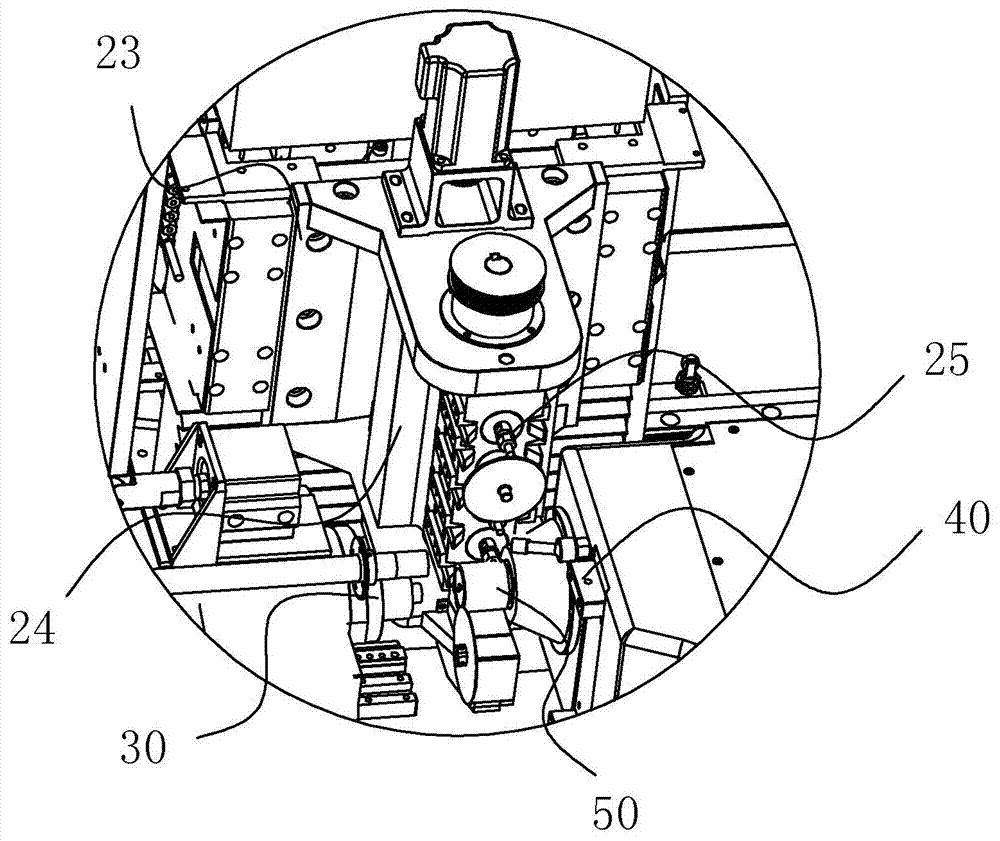
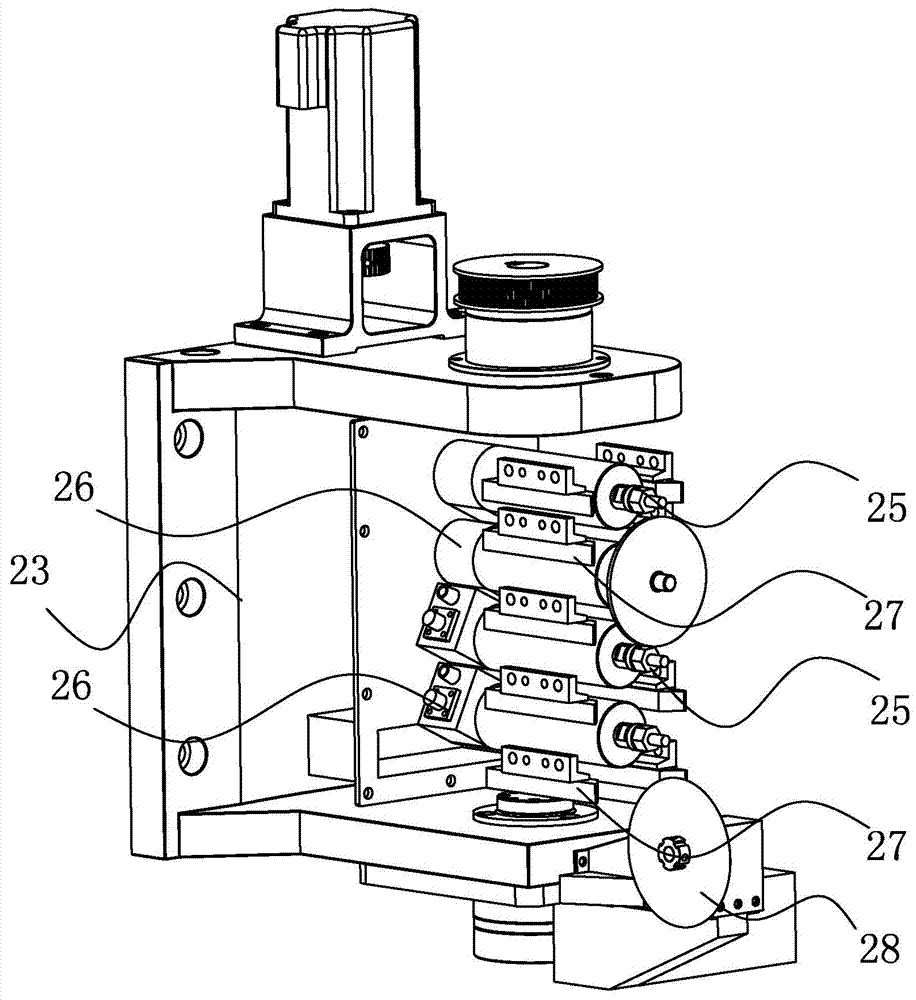
[0033] Such as Figure 1 to Figure 3 As shown, a kind of slanted bed dual-spindle turning-milling compound machine tool described in the present application includes a machine base 10, the upper part of the machine base 10 is inclined to set the bed 11, and the machine base 10 is provided with a power head 20 capable of changing the direction. The head 20 can rotate at any angle around an axis perpendicular to the bed 11 of the machine base 10 and can be fixed at a desired angle. Both sides of the power head 20 are respectively provided with a main shaft clamping device 30 and a sub shaft clamping device 40, the main shaft clamping device 30 and the sub shaft clamping device 40 are arranged oppositely, and the axis center of the main shaft clamping device 30 and the sub shaft mounting The axis center of the clamping device 40 is the same distance from the bed 11 of the machine base 10, the power head 20 can mill the side and end face of the workpiece on the main shaft clamping...

Embodiment 2

[0038] The main structure and principle of this embodiment are the same as those of Embodiment 1, and will not be repeated here. The difference from Embodiment 1 is:

[0039] The power head is a non-rotatable power head (not shown in the figure), and its main structure is the same as that of the prior art, including the axle box, in which the main power shaft is arranged, and the two ends of the main power shaft are connected with the axle box. Rotationally connected, the main power shaft is driven to rotate by the driver arranged on the upper part of the axle box. The main power shaft is provided with several direction-changing gear sets, and several direction-changing gear sets drive several power shafts to rotate respectively. One end of several power shafts protrudes from the outside of the axle box. The power shafts have many different orientations, including the power shaft facing the main shaft clamping device, the power shaft facing the sub shaft clamping device, and th...


PUM


Abstract

The invention belongs to the technical field of a numerically-controlled machine tool and particularly relates to a slant-bed, dual-primary shaft turning and milling combined machine tool. The machine tool comprises a machine base. A bed body of the machine base is obliquely arranged, so that iron chips which are generated during turning and milling are conveniently discharged out of the machine tool; workpieces on a primary shaft clamping device and a secondary shaft clamping device which are positioned on the two sides of a power head and are oppositely arranged can be machined by the power head of which the direction can be changed. Due to the fact that the power head can mill the end surface of the workpiece on the primary shaft clamping device and can also mill the end surface of the workpiece on the secondary shaft clamping device, the primary shaft clamping device and the secondary shaft clamping device are oppositely arranged, and the distance between the axis of the primary shaft clamping device and the bed body of the machine base is equal to the distance between the axis of the secondary shaft clamping device and the bed body of the machine base, compared with the technology that two shafts must be provided with two power heads in the prior art, the machine tool has the advantages that the power head is more simple and integrated in structure; due to the fact that the power head can rotate at any angle, compared with the power head with a fixed angle in the prior art, the power head has the advantage that the end surface with a special angle can be machined.

Description

technical field [0001] The application belongs to the technical field of numerical control machine tools, and in particular relates to a turning-milling compound machine tool with a slanted bed and double spindles. Background technique [0002] Turning and milling is an advanced cutting processing method that uses the synthetic motion of milling cutter rotation and workpiece rotation to realize the cutting process of the workpiece, so that the workpiece can meet the requirements of use in terms of shape accuracy, position accuracy, and machined surface integrity. Turning and milling combined machining is not simply combining turning and milling into one machine tool, but using turning and milling combined motion to complete various surface processing. A new cutting theory and cutting technology. [0003] In order to improve the processing efficiency and processing accuracy of complex special-shaped products, craftsmen have been seeking more efficient and precise processing ...

Claims


Application Information

Patent Timeline
Patent Type & Authority Patents(China)
IPC IPC(8): B23P23/02
CPCB23P23/02
Inventor 刘文聪张小兵
Owner 广东中聪智能装备有限公司
Learn More