
Cardiovascular compression device

A cardiovascular and support device technology, applied in the field of medical equipment, can solve problems such as high labor intensity, achieve the effect of reducing work intensity, preventing re-injury, and good compression effect

Inactive Publication Date: 2017-03-01
朱贵月
View PDF7 Cites 0 Cited by
  • Summary
  • Abstract
  • Description
  • Claims
  • Application Information

AI Technical Summary

Problems solved by technology

[0002] At present, clinically, manual compression is generally used for hemostasis at the puncture site after percutaneous puncture of the cardiovascular angiography, femoral artery extubation, and after extubation. Although the purpose of hemostasis can be achieved, it needs to be pressed for more than 30 minutes. Very large, causing pain to medical staff

Method used


Image

  • Cardiovascular compression device

Examples


Embodiment Construction

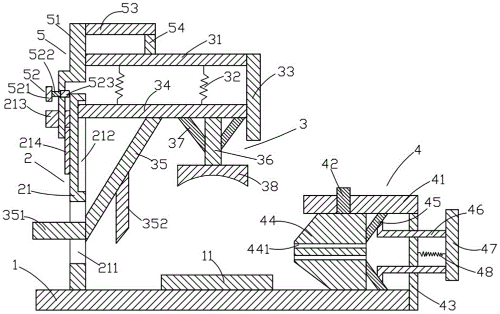
[0018] like figure 1 As shown, the compression device for cardiovascular imaging of the present invention includes a base 1, a support device 2 above the base 1, a compression device 3 on the right side of the support device 2, and a height adjustment device 5 above the compression device 3. And the fixing device 4 located on the right side of the pressing device 3 .

[0019] like figure 1 As shown, the base 1 is a cuboid, and the base 1 is placed horizontally. A sponge pad 11 is arranged above the base 1. The sponge pad 11 is a cuboid. The lower surface of the sponge pad 11 is in contact with the base 1. The upper surface is fixedly connected.

[0020] like figure 1 As shown, the support device 2 includes a first support column 21 , a first horizontal bar 213 located on the left side of the first support column 21 , and a first vertical bar 214 located below the first horizontal bar 213 . The first supporting column 21 is a cuboid, the first supporting column 21 is placed...


PUM


Abstract

The invention discloses an angiocardiography pressing device which comprises a base, a supporting device, a compression device, a height adjusting device and a fixing device, wherein a sponge cushion is arranged on the base; the supporting device comprises a first support pillar, a first horizontal rod and a first vertical rod; the height adjusting device comprises a first adjusting rod, a buckling device, a second horizontal rod and a second vertical rod; the compression device comprises a first support rod, first springs, a second support rod, a positioning rod, a first sloping plate, a support shaft, second sloping plates and a pressing plate; the fixing device comprises a first fixing rod, a first fixing column, a second fixing rod, a fixing block, third sloping plates, connecting rods, a fixing plate and a second spring; the left end of the fixing block is shaped like an isosceles trapezoid; the right end of the fixing block is shaped like a cuboid; second through holes penetrating through the left and right surfaces of the fixing block are formed in the fixing block. The angiocardiography pressing device disclosed by the invention is simple in structure and convenient to use; the angiocardiography pressing device can be used for compressing puncture parts for a long time, so that the working intensity of medical workers is reduced.

Description

technical field [0001] The invention relates to the technical field of medical devices, in particular to a compression device for cardiovascular imaging. Background technique [0002] At present, clinically, manual compression is generally used for hemostasis at the puncture site after percutaneous puncture of the cardiovascular angiography, femoral artery extubation, and after extubation. Although the purpose of hemostasis can be achieved, it needs to be pressed for more than 30 minutes. It is very large and brings pain to the medical staff. [0003] Therefore, it is necessary to provide a new technical solution to solve the above technical problems. Contents of the invention [0004] The object of the present invention is to provide a compression device for cardiovascular imaging that can effectively solve the above-mentioned technical problems. [0005] In order to solve the above technical problems, the present invention adopts the following technical solutions: [...

Claims


Application Information

Patent Timeline
Patent Type & Authority Patents(China)
IPC IPC(8): A61B17/12
CPCA61B17/12A61B2017/12004
Inventor 朱贵月
Owner 朱贵月
Learn More