
Damping circuit and led drive circuit with damping circuit

A damping circuit and control circuit technology, applied in the direction of electric lamp circuit layout, electric light source, electrical components, etc., can solve the problems of LED driver design difficulties, and achieve the effect of reducing the withstand voltage level, avoiding damage or inability to work

Active Publication Date: 2018-12-14
JOULWATT TECH INC LTD
View PDF5 Cites 0 Cited by
  • Summary
  • Abstract
  • Description
  • Claims
  • Application Information

AI Technical Summary

Problems solved by technology

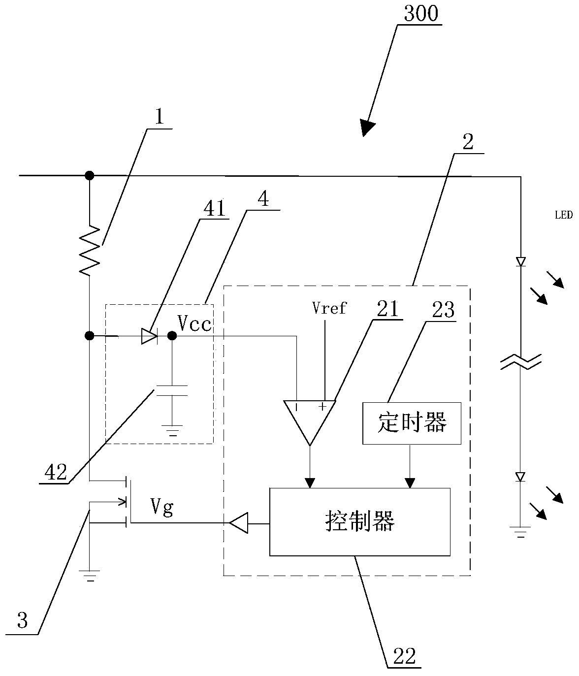
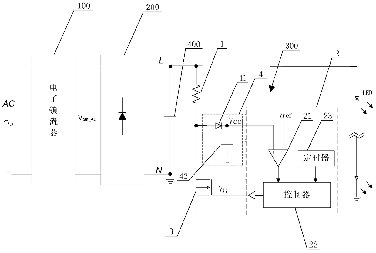
[0004] The present invention provides a damping circuit and an LED with a damping circuit in order to solve the problem that the high voltage output by the electronic ballast during the start-up stage brings difficulties to the design of the subsequent LED driver when the electronic ballast is used as power supply for the LED lamp. Drive circuit

Method used


Image

  • Damping circuit and led drive circuit with damping circuit
  • Damping circuit and led drive circuit with damping circuit
  • Damping circuit and led drive circuit with damping circuit

Examples


Embodiment Construction

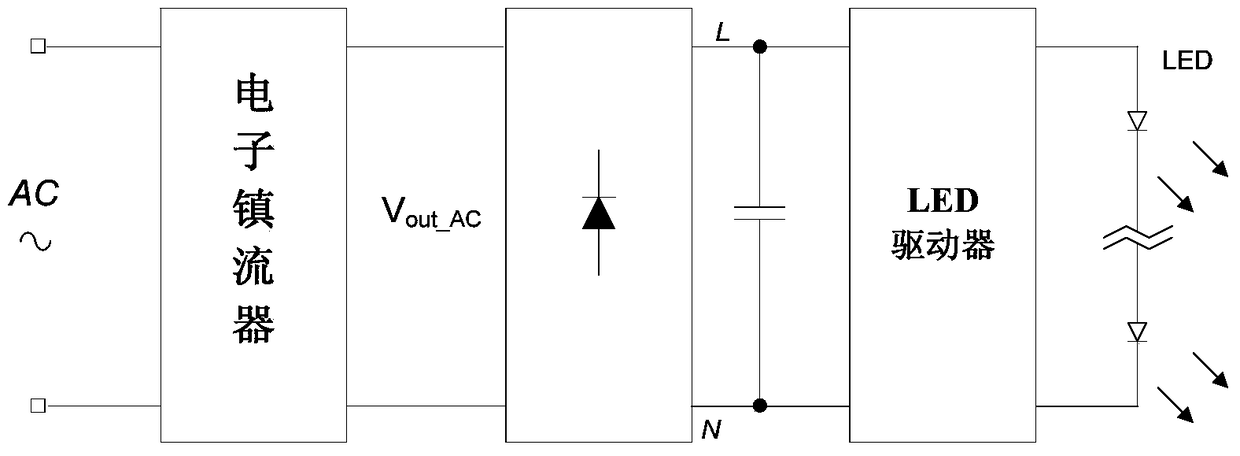
[0025] figure 1 Shown is the existing LED drive circuit, in this circuit, the AC high-frequency signal output by the electronic ballast is directly output to the LED driver after being rectified. However, since electronic ballasts are specially designed for fluorescent lamps, fluorescent lamps need to perform glow discharge during the lighting stage, and glow discharge requires a very high voltage. Therefore, the output of the electronic ballast includes two stages, one of which is the start-up stage, in which the electronic ballast outputs high voltage to make the fluorescent lamp glow, and when the fluorescent lamp is lit, the electronic ballast enters the steady-state stage, Output a normal working voltage of about 200V.

[0026] exist figure 1 In the process, the electronic ballast is directly connected to the LED driver. During the start-up phase of the electronic ballast, since the LED load is not connected, the load has no output current. At this time, the output of t...


PUM


Abstract

The invention provides a damping circuit and an LED driving circuit with the damping circuit. The damping circuit includes a damping element, a control circuit and a control switch. The damping element is electrically connected to the DC bus. The control circuit obtains the supply voltage from the DC bus and compares the supply voltage with the threshold voltage. When the DC bus voltage is higher than the threshold voltage, the control circuit outputs a first control signal. The control switch is electrically connected to the damping element and the control circuit respectively, and the control switch switches the damping element into the circuit based on the first control signal output by the control circuit. By setting a damping circuit in the LED drive circuit, the damping circuit can effectively restrain the voltage on the DC bus from continuing to rise during the startup phase, effectively reducing the withstand voltage level of the subsequent circuit, making the LED drive compatible with electronic ballasts.

Description

technical field [0001] The invention relates to the field of LED driving, and in particular to a damping circuit and an LED driving circuit with the damping circuit. Background technique [0002] The traditional electronic ballast is connected to the load of the fluorescent lamp, because the luminous efficiency of the fluorescent lamp is relatively low, there is a certain degree of environmental pollution. In today's energy saving and emission reduction, replacing fluorescent lamps with LED lamps has become a trend. In order to achieve direct replacement, LED lamps not only need to be able to accept ordinary mains electricity for their power supply, but also need to be able to be directly connected, that is, the electronic ballast of fluorescent lamps as their power supply. However, the output of the electronic ballast is a high-frequency AC signal, while the LED lamp needs a DC power supply, and the two cannot be directly matched. Therefore, it is usually necessary to rec...

Claims


Application Information

Patent Timeline
Patent Type & Authority Patents(China)
IPC IPC(8): H05B37/02H05B44/00
Inventor 张军明胡燊刚季悦黄必亮任远程周逊伟
Owner JOULWATT TECH INC LTD
Learn More