Automatic floating-type lock gate

A technology for gates and gate piers, which is applied in the field of floating automatic gates, and can solve problems such as inability to automatically adjust, large force on gate plates and gate piers, and disturbed water flow conditions.

Active Publication Date: 2015-07-22
SHANDONG AGRICULTURAL UNIVERSITY
View PDF7 Cites 3 Cited by
  • Summary
  • Abstract
  • Description
  • Claims
  • Application Information

AI Technical Summary

Problems solved by technology

During the opening process of the horizontal axis automatic flap gate, the gate above the transverse support structure rotates around the transverse support structure along the direction of water flow, while the gate below the transverse support structure rotates around the transverse support structure against the direction of water flow. Enough force is required to turn the gate over, and the force on the gate and the gate pier is too large, which is not conducive to the stability of the gate.
[0006] Third, when the horizontal axis hydraulic automatic flap gate is in the process of water discharge, the entire gate is in the water flow, and for the water discharge, the gate produces a huge resistance and seriously disturbs the state of the water flow , which seriously affects the discharge capacity of the water flow
[0007] Fourth, the horizontal-axis hydraulic automatic flap gate, due to factors such as the supporting conditions for controlling the operation of the gate, the pressure of the gate plate, the discharge of the cavity behind the gate, the jacking of the downstream water level, and the negative pressure in the cavity behind the gate, the gate is in operation. There will be a "slapping" phenomenon that periodically slaps the pier or sill back and forth, which is extremely destructive
[0008] Fifth, the horizontal-axis hydraulic automatic flap gate requires a sufficiently large water level when it is opened, so that the opening of the gate is greatly restricted, the opening is not flexible, and some even cannot be opened; The water level can only be closed, which will affect the normal water storage
[0009] Sixth, due to the characteristics of the support structure of the horizontal-axis automatic flap gate, the opening of the gate is limited. adjust

Method used


Image

  • Automatic floating-type lock gate
  • Automatic floating-type lock gate
  • Automatic floating-type lock gate

Examples


Embodiment Construction

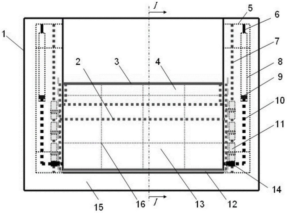
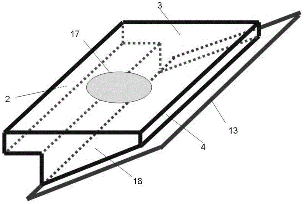
[0025] Such as figure 1 , figure 2 , image 3 As shown, the device mainly includes a lock chamber, a floating automatic gate, a roller groove, a track, a water stop, and a hydraulic damping device.

[0026] The gate pier is a symmetrically arranged concrete structure, reinforced concrete structure, or masonry structure, etc., depending on the depth of the upstream water. The safe operation of the gate is the basis; the gate bottom plate is a reinforced concrete structure, or a concrete structure, or a masonry structure, etc., depending on the depth of the upstream water; the gate piers on both sides and the gate bottom plate are poured on site, and poured into a complete overall structure , to increase its stability; the floating automatic gate is made of steel structure, prefabricated reinforced concrete structure or other materials with certain rigidity and strength, and the texture of the gate is required to be uniform. Determined to ensure that under the action of buoy...


PUM


Abstract

The invention relates to an automatic floating-type lock gate. The automatic floating-type lock gate comprises a lock chamber, rolling wheel grooves, rails, a lock gate body, rolling wheels, a water stop and hydraulic damping devices. Gate piers and a gate lock base plate form the lock chamber; the lock gate body is installed between the gate piers on the two sides; the rolling wheels are arranged on the positions, on the two sides, of the bottom of a bottom face plate, the rolling wheels are distributed on the rails, the rails can be fixed onto the bottom faces of the rolling wheel grooves, and the hydraulic damping devices are fixed onto the inner sides of the rolling wheel grooves. By means of the automatic floating-type lock gate, the opening degree of the lock gate can be automatically adjusted at any time with the high-low changes of water levels of upland water, the gradual opening performance of the lock gate is good, and the opening and the closing are more strength-saving and flexible. The automatic floating-type lock gate does not need external power, and the automatic opening and closing of the lock gate can be achieved totally through the upland water.

Description

[0001] 1. Fields: [0002] The invention relates to a floating automatic gate. 2. Background technology [0003] As the most widely used hydraulic structure at present, the sluice has been fully utilized in a large number of water conservancy projects and plays a huge role! There are many types of hydraulic gates, which can be divided into beam gates, plane gates, roof gates, arc gates, sector gates, drum gates, round tube gates, arch gates, spherical gates, floating box gates, etc. according to their structural characteristics. , all kinds of gates have different characteristics due to structural differences. However, the general gate mainly relies on external force to lift the gate, so that the water flows downstream from the water passage between the gate and the gate floor to complete the appointment of water discharge, but the required lifting is relatively large, and a special opening and closing room needs to be built. , the cost is high, and the operation is cumberso...

Claims


Application Information

Patent Timeline
Patent Type & Authority Applications(China)
IPC IPC(8): E02B7/50
CPCE02B7/50
Inventor 王春堂王世龑
Owner SHANDONG AGRICULTURAL UNIVERSITY
Why Eureka
Try Eureka