
A printing base and inkjet printing method

An inkjet printing and abutment technology, applied in printing devices, copying/marking methods, printing, etc., can solve the problems of increasing the width of the frame of the liquid crystal display panel, and achieve the effect of increasing the area and reducing the width of the frame

Active Publication Date: 2017-05-31
BOE TECH GRP CO LTD
View PDF5 Cites 0 Cited by
  • Summary
  • Abstract
  • Description
  • Claims
  • Application Information

AI Technical Summary

Problems solved by technology

In addition, the test area is not used to display images, therefore, the bezel width of the LCD panel is increased

Method used


Image

  • A printing base and inkjet printing method
  • A printing base and inkjet printing method
  • A printing base and inkjet printing method

Examples


Embodiment Construction

[0022] In order to make the object, technical solution and advantages of the present invention clearer, the implementation manner of the present invention will be further described in detail below in conjunction with the accompanying drawings.

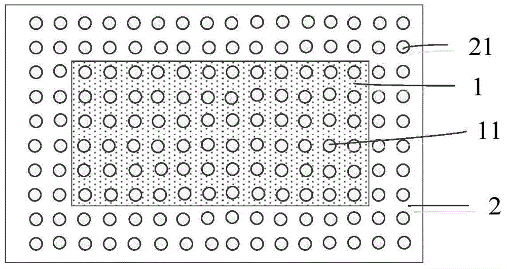
[0023] An embodiment of the present invention provides a printing platform, see figure 1 with figure 2 , the printing base includes: a loading base 1 , an extension base 2 , a vacuum pump 3 and an air injection valve 4 .

[0024] The extension base 2 is located around the object loading base 1, the object loading base 1 has at least one adsorption hole 11 for absorbing the substrate 5, and the extension base 2 has at least one injection hole 21;

[0025] Vacuum pump 3 is connected with at least one adsorption hole 11, and gas injection valve 4 is connected with at least one injection hole 21, and gas injection valve 4 is used to inject gas around object base 1 through at least one injection hole 21, so that the object base 1 A solve...


PUM

PropertyMeasurementUnit
widthaaaaaaaaaa

Abstract

The invention discloses a printing base and an inkjet printing method, belonging to the field of light-emitting device manufacturing. The printing base includes: an object loading base, an extension base, a vacuum pump and an air jet valve; the extension base is located around the object loading base, the object loading base has at least one adsorption hole for absorbing the substrate, and the extension base has At least one injection hole; the vacuum pump is connected with at least one adsorption hole, and the gas injection valve is connected with at least one injection hole, and the gas injection valve is used to inject gas around the object base platform through at least one injection hole, so that the substrate on the object base platform A solvent atmosphere is formed all around, so that the dry atmosphere of the edge pixels and the middle pixels in the substrate are consistent. The present invention can remove the test area around the display area in the substrate by increasing the extension base around the object-carrying base, thereby increasing the area of ​​the display area and further reducing the frame width of the liquid crystal display panel.

Description

technical field [0001] The invention relates to the field of light-emitting device manufacturing, in particular to a printing base and an inkjet printing method. Background technique [0002] In the preparation process of PLED (English: Polymer Light-Emitting Diode; Chinese: Polymer Light-Emitting Diode), inkjet printing technology is usually used to form red, green, and blue primary color light-emitting pixels. That is, the pre-patterned substrate of ITO (English: Indium Tin Oxide; Chinese: Indium Tin Oxide) is adsorbed on the printing platform, and the hole transport material and the solution of red, green and blue light-emitting materials are sprayed. In the sub-pixel pits on the substrate, light-emitting pixels of red, green and blue primary colors are formed. However, the drying atmosphere of the edge pixels of the substrate is inconsistent with that of the middle pixels, which will cause the drying speed of the edge pixels to be greater than that of the middle pixels,...

Claims


Application Information

Patent Timeline
Patent Type & Authority Patents(China)
IPC IPC(8): B41J2/01B41J11/00
CPCH10K59/88H10K71/135B41J2/01B41M5/0011H10K71/00H10K71/441H10K99/00B41J11/0015
Inventor 胡春静孙力
Owner BOE TECH GRP CO LTD
Learn More