
Cutting device for petroleum pipeline

A technology for oil pipelines and cutting devices, which is applied to cutters, pipe shearing devices, shearing devices and other directions for shearing machine devices, can solve the problems of uneven cutting, affecting sealing effect, low efficiency, etc., and achieves deepening cutting thickness, Guaranteed cutting effect

Inactive Publication Date: 2015-07-22
CHENGDU LAIBAO PETROLEUM EQUIP
View PDF7 Cites 4 Cited by
  • Summary
  • Abstract
  • Description
  • Claims
  • Application Information

AI Technical Summary

Problems solved by technology

[0003] In order to solve defects such as uneven cutting, affecting sealing effect, and low efficiency, the present invention provides an oil pipeline cutting machine

Method used


Image

  • Cutting device for petroleum pipeline
  • Cutting device for petroleum pipeline
  • Cutting device for petroleum pipeline

Examples


Embodiment 1

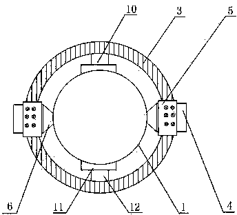
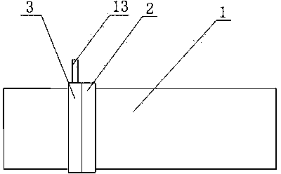
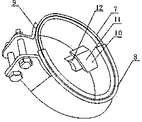
[0017] Such as figure 1 , figure 2 , image 3 , Figure 4 As shown, it includes a hoop 2 sleeved on the oil pipeline 1, a ring hole 14 is opened on the side of the hoop 2, a cutting ring 3, and a ring 15 concentric with the cutting ring 3 are fixed on one side of the cutting ring 3 And the cutter 4 fixed on the other side of the cutting ring 3, the ring 15 is rotated and arranged in the ring hole 14; the cutter 4 includes a cutting seat 5, a cutting knife 6, and the cutting seat 5 is a cavity structure with openings on both sides. The cutting knife 6 runs through the cutting seat 5; the upper surface of the cutting seat 5 and the back of the cutting knife 6 are provided with corresponding holes, and the cutting seat 5 and the cutting knife 6 are connected by bolts that simultaneously pass through the holes on the cutting seat 5 and the back of the cutting knife 6. connection, the cutting seat 5 is fixed on the upper surface of the cutting ring 3; the hoop 2 includes a semi...

Embodiment 2

[0020] On the basis of Embodiment 1, this embodiment also includes a card seat 10 arranged on the inner surface of the hoop 2; the card seat 10 includes a base 11, a card slot 12 fixed on the base 11, and the front end of the card slot 12 is an arc shaped structure, the base 11 is fixed on the inner surface of the hoop 2.

[0021] In this embodiment, the front end of the clamping groove 12 has an arc-shaped structure, so that the hoop 2 can be sleeved on the oil pipeline 1 more stably.

Embodiment 3

[0023] On the basis of embodiment 1 or embodiment 2, this embodiment further includes a handle 13 fixed on the side of the cutting ring 3 .

[0024] The handle 13 arranged on the cutting ring 3 can rotate the cutting ring 3 conveniently, so that the cutter 6 on the cutting ring 3 can cut the oil pipeline 1 more evenly.


PUM


Abstract

The invention discloses a cutting device for a petroleum pipeline. The cutting device for the petroleum pipeline comprises a hoop which is arranged on the petroleum pipeline in a sleeving mode, wherein holes are formed in the side faces of the hoop. The cutting device for the petroleum pipeline further comprises a cutting ring, a circular ring and cutters, wherein the circular ring is fixed to one side face of the cutting ring and is concentric with the cutting ring, the cutters are fixed to the left side and right side of the other side face of the cutting ring respectively, and the circular ring penetrates through the holes formed in the side faces of the hoop to be arranged in the hoop in a rotary mode. Each cutter comprises a cutting base and a cutting knife, wherein the cutting base is of a cavity structure with the two side faces being open, and the cutting knife penetrates through the openings in the two side faces of the cutting base to be to be arranged in the cutting base. According to the cutting device for the petroleum pipeline, the position of the cutting ring is fixed through the hoop, and it is guaranteed that the petroleum pipeline is cut through the cutting knives smoothly. The two end faces of a semicircular shell A are arranged in the two end faces of a semicircular shell B in a sliding mode respectively, in this way, the size of the hoop can be slightly adjusted, and the cutting device can be suitable for petroleum pipelines in different sizes to a certain extent.

Description

technical field [0001] The invention relates to a cutting mechanism, in particular to a cutting device for oil pipelines. Background technique [0002] In the oil industry, it is necessary to lay long pipelines for oil transportation, but because most of the oil pipelines are laid in relatively harsh environments, leakage and rupture often occur. If the damage is too large, repair welding cannot be done. , it is necessary to cut off the damaged part and replace it with a new pipe. During the replacement process, it is necessary to ensure that the cut pipe is flat. But existing operation is generally surrounded the outer wall of oil pipeline by a people with circle band, and another people draws a line along circle band with special stone pen, then cuts along the line drawn. The problem with this method is that when the diameter of the pipe is large, two people must operate at the same time to complete the work of drawing the line, which is a waste of manpower, and cutting a...

Claims


Application Information

Patent Timeline
Patent Type & Authority Applications(China)
IPC IPC(8): B23D21/04B23D35/00
Inventor 谭正怀
Owner CHENGDU LAIBAO PETROLEUM EQUIP
Learn More