Hole drilling positioning die of top beam spring sleeve

The technology of a spring sleeve and a positioning mold, which is applied in the direction of a drilling mold for a workpiece, etc., can solve the problems of reducing the work efficiency of the operator, inconvenient assembly of the top beam bracket, and failing to achieve the uniformity of the workpiece processing, and achieves a simple structure and reduced Labor-intensive, easy-to-make effects

Inactive Publication Date: 2015-07-22
六盘水宏山托辊制造有限公司
View PDF7 Cites 2 Cited by
  • Summary
  • Abstract
  • Description
  • Claims
  • Application Information

AI Technical Summary

Problems solved by technology

[0002] Originally, each spring sleeve drilling hole needs to be positioned by drawing a line, and it takes a lot of time to control the rotation of the guide rod during drilling, which greatly reduces the work efficiency of the operator, and does not achieve the uniformity of workpiece processing. The pairing of beams and the assembly of brackets bring great inconvenience

Method used


Image

  • Hole drilling positioning die of top beam spring sleeve
  • Hole drilling positioning die of top beam spring sleeve

Examples


Embodiment Construction

[0012] The present invention will be described in further detail below in conjunction with the accompanying drawings, but not as any limitation to the present invention.

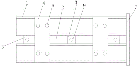
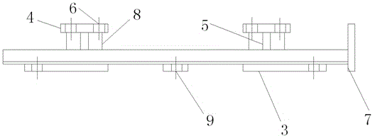
[0013] Embodiment of the present invention: a drilling positioning mold for a top beam spring sleeve, as shown in the accompanying drawings, includes at least two profiles 1 with a "U"-shaped cross section, and the inside of the "U"-shaped profiles 1 The net width is 1 / 3~1 / 2 of the diameter of the top beam spring sleeve, and its internal clear height is greater than the radius of the top beam spring sleeve. The "U" profile 1 is laid in parallel to form a gap 2, and the connecting plate 3 is placed At the bottom of the "U" profile 1, the "U" profile 1 is connected as a whole, the positioning plate 4 is placed directly above the "U" profile 1, and the positioning plate 4 and the connecting plate 3 in the gap 2 are provided. The support plate 5 realizes the fixation of the positioning plate 4, and a reinforcing...


PUM


Abstract

The invention discloses a hole drilling positioning die of a top beam spring sleeve. The hole drilling positioning die comprises at least two sectional materials with U-shaped cross sections, the U-shaped sectional materials are laid in parallel and form a gap, a connecting plate is placed at the bottom of each U-shaped sectional material so that the U-shaped sectional materials can be connected together, a positioning plate is placed over each U-shaped sectional material, a supporting plate is arranged between each positioning plate and the position, at the gap, of the corresponding connecting plate to fix the positioning plate, a hole drilling positioning hole is formed in each positioning plate and is located over a center line of one single U-shaped sectional material, and U-shaped sectional material axial limiting is achieved on one sides of the U-shaped sectional materials by arranging baffles. By means of the hole drilling positioning die, the U-shaped sectional materials are arranged, so that radial rotation of the spring sleeve is prevented; the baffles are arranged for preventing axial movement of the spring sleeve, and the position of a machining hole in the spring sleeve can be effectively determined through the positioning plates above the baffles and the hole drilling positioning holes.

Description

technical field [0001] The invention relates to a drilling positioning mold for a top beam spring sleeve, belonging to the technical field of mechanical processing auxiliary devices. Background technique [0002] Originally, each spring sleeve drilling hole needs to be positioned by drawing a line, and it takes a lot of time to control the rotation of the guide rod during drilling, which greatly reduces the work efficiency of the operator, and does not achieve the uniformity of workpiece processing. The pairing of beams and the assembly of brackets bring great inconvenience. Contents of the invention [0003] The purpose of the present invention is to provide a drilling positioning mold for the top beam spring sleeve in view of the above defects in the prior art, which greatly reduces the labor intensity, improves the work efficiency, and also improves the uniformity of the sleeve drilling. performance and accuracy to overcome the deficiencies of existing technologies. ...

Claims


Application Information

Patent Timeline
IPC IPC(8): B23B47/28
CPCB23B47/28
Inventor 陈建华
Owner 六盘水宏山托辊制造有限公司
Why Eureka
Try Eureka