Eureka AIR delivers breakthrough ideas for toughest innovation challenges, trusted by R&D personnel around the world.

A kind of inverted core assembly method

A technology of core assembly and lock core, which is applied in the direction of cores, casting molding equipment, casting molds, etc., can solve the problems of sand cores not being assembled in place, X-direction size deviation, Y-direction deviation, etc., so as to improve product qualification rate and reduce Dimensional variation and the effect of improving productivity

Active Publication Date: 2018-07-24
TONGLIN CASTING IND
View PDF6 Cites 0 Cited by
  • Summary
  • Abstract
  • Description
  • Claims
  • Application Information

AI Technical Summary

Problems solved by technology

[0003] The main points of the vertical core assembly method are: the lower plane of the cylinder bore core is used as the positioning surface; the adhesive is applied between the sand cores, and the distance between the cylinder bore cores is compressed by the lock core screw, so that the sand core wears less during the movement process. The size of the sand core is large and the wear amount of each sand core is different, which will easily cause the positioning surface to be uneven, resulting in a dimensional deviation in the X direction (the direction from the crankshaft hole to the cylinder hole), and a deviation in the Z direction (the width direction of the crankshaft hole) due to the design gap of the sand core. A certain thickness, resulting in deviation in the Y direction (direction from the first crankshaft hole to the fifth crankshaft hole)
[0004] The main points of the horizontal core assembly method are: the inclined cone surface on the top of the cylinder hole core is the positioning surface, the adhesive is applied between the sand cores, and the lock core screw is used to compress the distance between the cylinder hole cores, and the sand cores are easy to break when placed horizontally; The positioning of the inclined cone surface may easily cause the sand core to not be combined in place, resulting in positioning errors and resulting in X-direction dimension deviations, and due to the existence of a certain thickness of the adhesive, resulting in Y-direction deviations

Method used


Image

  • A kind of inverted core assembly method
  • A kind of inverted core assembly method
  • A kind of inverted core assembly method

Examples


Embodiment 1

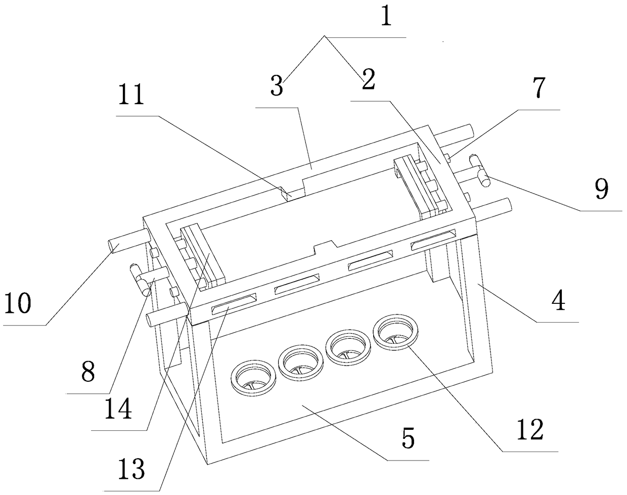
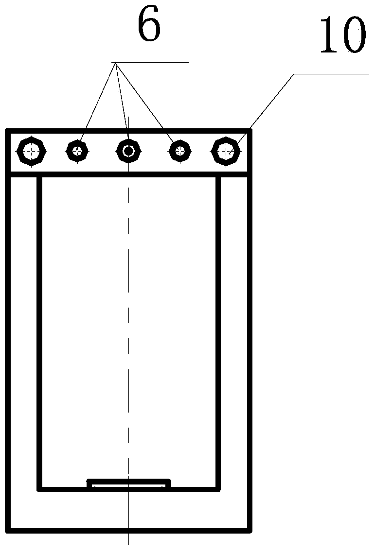
[0026] refer to figure 1 with figure 2 As shown, the entire structure is composed of an upper frame 1, a bracket 4 and a base 5. The upper frame 1 is composed of an adjustment end 2 and a limit end 3. The adjustment end 2 is provided with a handle 10 and an adjustment hole 6. The limit plate 14 passes through the The guide rod 7 and the adjusting screw rod 8 passing through the adjusting hole 6 are connected with the adjusting end 2, and the adjusting screw rod 8 is also provided with an adjusting handle 9; Limiting hole 12 with washer.

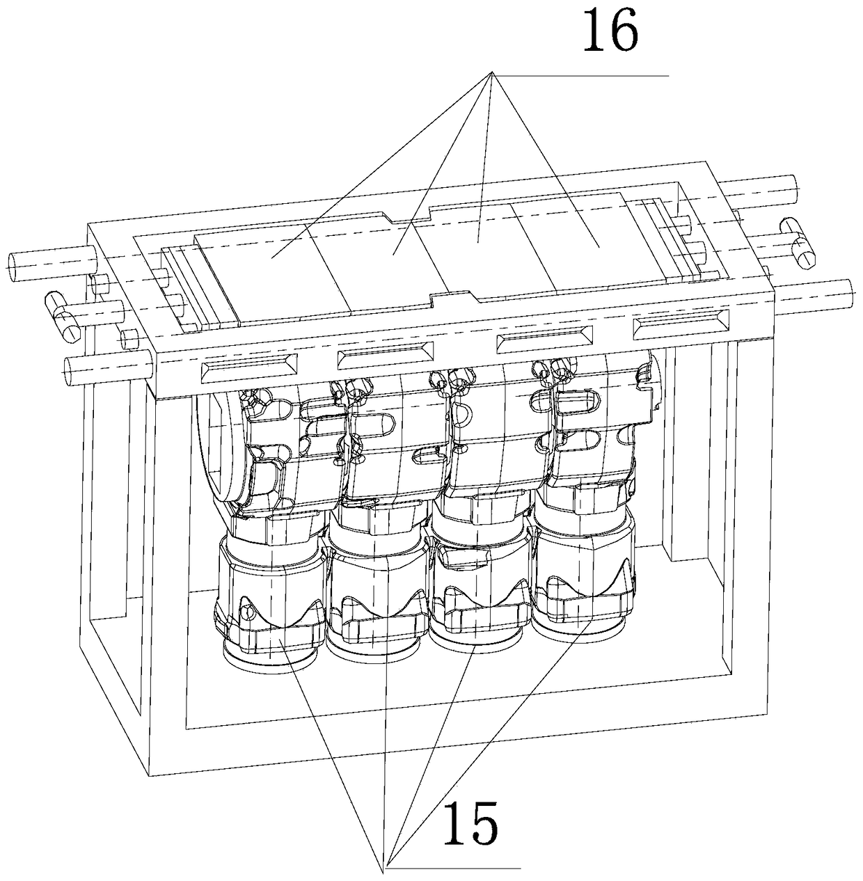
[0027] For the inverted core assembly method provided by the present invention, refer to image 3 shown, including the following steps

[0028] a. Lift the handle 10 to remove the upper frame 1 from the bracket 4, and place the lock cylinder 15 to be adapted in a vertical manner with the cylinder hole facing down and the crankshaft hole facing up in the limit hole 12 with the washer superior;

[0029] b. Then the upper frame 1 is arrang...


PUM


Abstract

The invention discloses an inverted core assembly method. Through a specific device, the plane of the middle section of each tank hole core is used as a positioning plane during core assembly. The plane is not prone to get worn and collided and is scientific and the relative size between the tank hole cores after the cores are locked can be well guaranteed. By adopting the core assembly method and a lock core rack, compared with the prior at, for the method, the size error of a lock core in each direction is greatly reduced, the yield is increased and the production efficiency is improved.

Description

technical field [0001] The invention belongs to the field of casting technology, in particular to a casting technology suitable for engine cylinder body castings. Background technique [0002] In the prior art, when working on the lock cylinder, the vertical core assembly method (place the cylinder bore core with the crankshaft hole facing down and the cylinder bore upward) or the horizontal core assembly method (place the cylinder core cores horizontally side by side) . But both methods have their limitations. [0003] The main points of the vertical core assembly method are: the lower plane of the cylinder bore core is used as the positioning surface; the adhesive is applied between the sand cores, and the distance between the cylinder bore cores is compressed by the lock core screw, so that the sand core wears less during the movement process. The size of the sand core is large and the wear amount of each sand core is different, which will easily cause the positioning s...

Claims


Application Information

Patent Timeline
Patent Type & Authority Patents(China)
IPC IPC(8): B22C9/10
CPCB22C9/108
Inventor 陈科
Owner TONGLIN CASTING IND
Why Eureka
Eureka Blog
Learn More