
Movement of mechanical sphygmomanometer for self-calibration production technology

A production process and blood pressure meter technology, which is applied in vascular assessment, cardiac catheterization, etc., can solve the problems of complex structure, high manufacturing, assembly and calibration costs, and high manufacturing precision, and achieve the goal of simplifying the movement, low cost, and improving production efficiency Effect

Active Publication Date: 2015-07-22
HONSUN NANTONG
View PDF6 Cites 2 Cited by
  • Summary
  • Abstract
  • Description
  • Claims
  • Application Information

AI Technical Summary

Problems solved by technology

Ordinary mechanical sphygmomanometer movements need to be equipped with calibration components. The general calibration components include calibration discs, calibration plates, and calibration plate screws. The distance between the center of the thimble pin hole and the rotation center of the plate gear is adjusted through the calibration plate, that is, the crank in the crank slider mechanism is adjusted. When the crank length is properly adjusted, tighten the correction plate screw to lock the crank length. The adjustment mechanism of ordinary mechanical blood pressure gauges has the defects of complex structure, high manufacturing precision, and high manufacturing, assembly and calibration costs.

Method used


Image

  • Movement of mechanical sphygmomanometer for self-calibration production technology
  • Movement of mechanical sphygmomanometer for self-calibration production technology

Examples


Embodiment 1

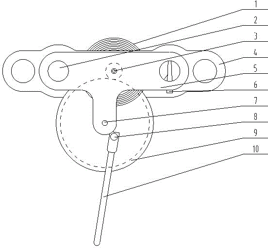
[0016] Embodiment 1: see figure 1 , the movement of a mechanical sphygmomanometer used for the self-calibration production process, the movement is composed of the following, an upper splint, a lower splint, a movement column arranged between the upper splint and the lower splint, a pointer shaft, and a device for providing elastic recovery The hairspring, the hairspring pin for fixing the hairspring, and the crank connecting rod. The upper splint is fixedly connected to the lower splint through the movement column. The pointer shaft is installed in the holes of the upper splint and the lower splint and can rotate. One end of the hairspring 1 It is fixed on the pointer shaft 3, and the other end is fixed on the movement column 2 through the hairspring pin 6, and a gear is arranged on the pointer shaft.

Embodiment 2

[0017] Example 2: see figure 1 , as an improvement of the present invention, the crank connecting rod is composed of a piece gear 9, a piece gear shaft 7, a thimble pin 10 and a thimble post 8, and the piece gear shaft 7 is installed in the holes of the upper clamping plate and the lower clamping plate and is connected with The piece gear 9 is fixedly connected, and the piece gear 9 meshes with the gear on the pointer shaft 3; the piece gear 9 forms a pin connection with the thimble pin 10 through the thimble column 8; the other end of the thimble pin 10 is in contact with the air pressure elastic diaphragm box of the mechanical blood pressure gauge connected.

Embodiment 3

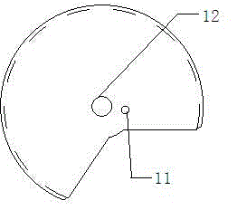
[0018] Embodiment 3: see figure 1 , as an improvement of the present invention, a small round hole 11 is provided on the said piece gear, and said thimble column is fixed on the piece gear 9 through the small round hole 11 .


PUM


Abstract

The invention relates to a movement of a mechanical sphygmomanometer for a self-calibration production technology. The movement of the mechanical sphygmomanometer for the self-calibration production technology is characterized in that the movement is composed of an upper clamping plate, a lower clamping plate, movement columns arranged between the upper clamping plate and the lower clamping plate, a pointer shaft, a hairspring providing elastic recovery, a hairspring pin for fixing the hairspring and a crank connecting rod, the upper clamping plate is fixedly connected with the lower clamping plate through the movement columns, the pointer shaft is installed in holes of the upper clamping plate and the lower clamping plate and can rotate, one end of the hairspring is fixed on the pointer shaft, the other end of the hairspring is fixed on one movement columns through the hairspring pin, and a gear is arranged on the pointer shaft.

Description

technical field [0001] The invention relates to a movement, in particular to a movement of a mechanical sphygmomanometer used in a self-calibration production process, and belongs to the technical field of medical equipment. Background technique [0002] With the development of the economy and the progress of the society, consumers are paying more and more attention to their own health care. The blood pressure meter has become one of the necessary medical equipment in many families. Converted to rotation of the pointer axis. The movement of an ordinary mechanical sphygmomanometer consists of a crank slider mechanism in series with a gear mechanism. Due to errors in the manufacture of blood pressure gauge parts, the common mechanical blood pressure gauge movement has an adjustment mechanism for adjusting the length of the crank so that the offset of the blood pressure gauge pointer can correspond to the scale on the pre-printed dial. Ordinary mechanical sphygmomanometer mov...

Claims


Application Information

Patent Timeline
IPC IPC(8): A61B5/021
Inventor 李名尧
Owner HONSUN NANTONG
Learn More